Jigsaw blade

A thorn saw blade and thorn saw technology, which is applied to metal sawing equipment, tools of sawing machine devices, metal processing equipment, etc., can solve problems such as affecting the quality of the cutting surface, and achieve the effect of improving cutting power

Active Publication Date: 2010-07-21
ROBERT BOSCH GMBH
View PDF2 Cites 4 Cited by
  • Summary
  • Abstract
  • Description
  • Claims
  • Application Information

AI Technical Summary

Problems solved by technology

[0003] In principle, however, the left-right split tooth row has the disadvantage of a relatively wide incision, which according to DE 20109811U1 leads to better discharge of the guide sawdust
However, if in the continuous sawing process, after the saw blade start

Method used


Image

  • Jigsaw blade
  • Jigsaw blade
  • Jigsaw blade

Examples


Embodiment Construction

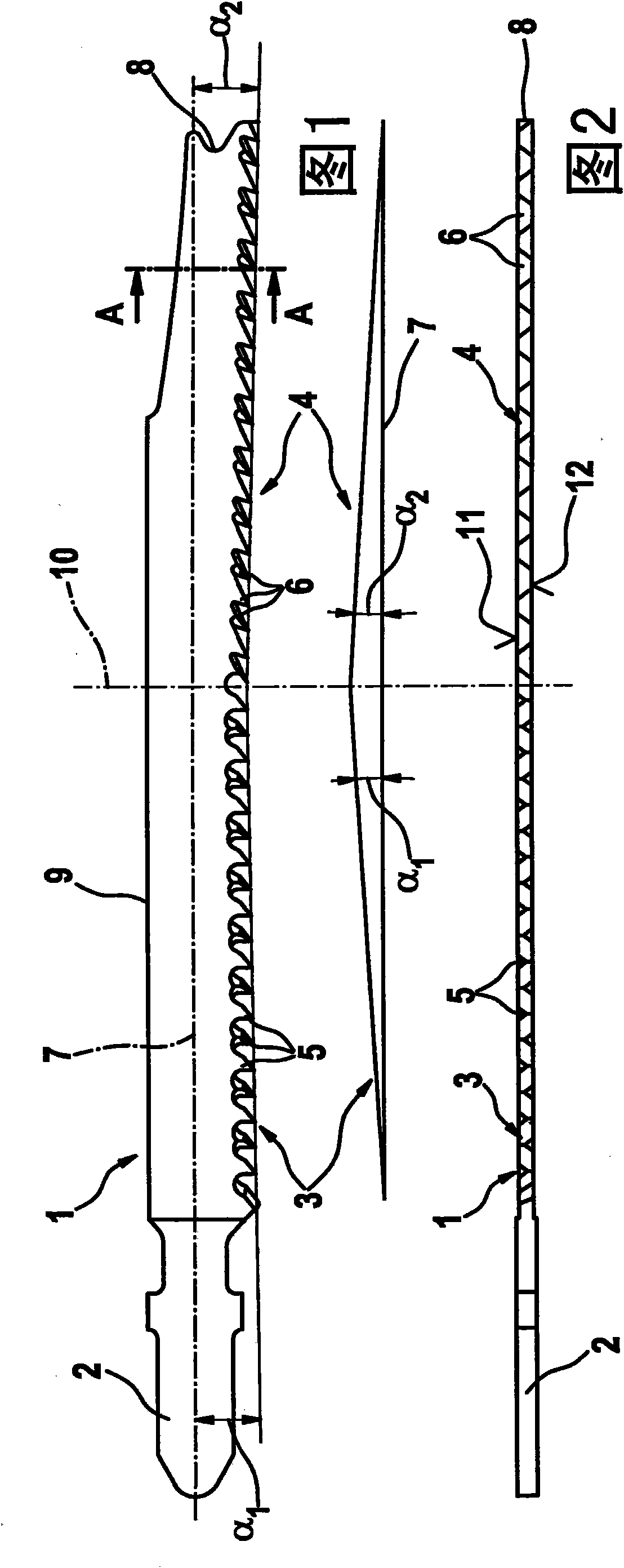
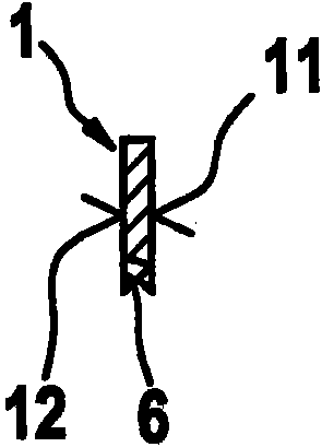
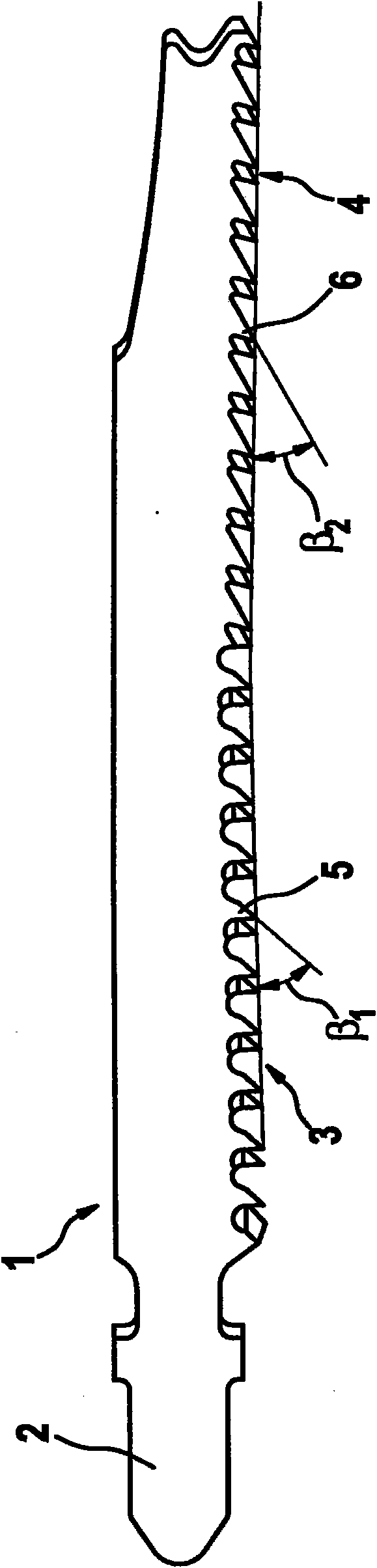
[0020] figure 1 The jigsaw blade 1 described in has a shank 2 by means of which the jigsaw blade is clamped in a motorized saw. On the jigsaw blade, the teeth 5, 6 are distributed on the first sawtooth row 3 adjacent to the handle and the second sawtooth row 4 adjacent to the tip 8 of the saw blade, and the two sawtooth rows 3, 4 are arranged one behind the other and lie in a common plane. The teeth 5 and 6 of the two tooth rows 3 or 4 are each directed towards the shank 2 . The two tooth rows 3 and 4 have approximately the same length, the transition between the tooth rows 3 and 4 being indicated by a straight line 10 . The longitudinal axis of the jigsaw blade 1 is provided with reference numeral 7 , which is at the same time the feed direction or cutting direction of the saw blade 1 , the back side 9 of the saw blade extending parallel to the longitudinal axis 7 .

[0021] The two tooth rows 3 and 4 have an angle α with respect to the longitudinal axis or direction of fe...


PUM


Abstract

The invention relates to a jigsaw blade (1) having one first (3) and one second (4) row of saw teeth disposed at an angle to each other. Both the first and the second row of saw teeth encompass an angle relative to the push or cut direction, the angle (alpha1) of the first row of saw teeth being directed conversely to the angle (alpha2) of the second row of saw teeth.

Description

technical field [0001] The invention relates to a jigsaw blade according to the preamble of claim 1 . Background technique [0002] A jigsaw blade of this type is known from DE 20109811 U1. The jigsaw blade has a main tooth row with a plurality of teeth of the same type, which are formed without left and right teeth divisions, so that the saw blade has smooth sides without protruding teeth. There are a plurality of initial cutting teeth in front of the main tooth row, and the initial cutting teeth are arranged close to the shank of the jigsaw blade and are provided with left and right divided teeth. The initial cutting teeth should prevent the cutting edge at the upper side of the workpiece from being broken. According to a variant described in DE 20109811 U1, the dentition with initial incisors runs at an angle to the main dentition, so that a further improvement of the cutting pattern is achieved. [0003] In principle, however, a left-right split tooth row has the disa...

Claims


Application Information

Patent Timeline
IPC IPC(8): B23D61/12
CPCB23D61/128B23D61/121
Inventor D·格洛丽蒙德M·科克
Owner ROBERT BOSCH GMBH
Why Eureka
Try Eureka