Efficient electromagnetic pulse valve and working method thereof

An electromagnetic pulse valve, high-efficiency technology, applied in the direction of the valve operation/release device, valve details, diaphragm valve, etc., can solve the problems of the dust removal effect of the dust collector, the air supply time becomes longer, the diaphragm cracks and fails, etc., to achieve enhanced reliability Performance and service life, improved circulation efficiency, and fast pulse action

Pending Publication Date: 2020-02-04
王金水
View PDF0 Cites 3 Cited by
  • Summary
  • Abstract
  • Description
  • Claims
  • Application Information

AI Technical Summary

Problems solved by technology

[0003] The existing pulse valve has the following defects: (1) Due to the relatively small orifice (about Φ1.5), it will be blocked by dust and other pollutants, which will reduce the flow of gas flowing from the bottom of the diaphragm to the top of the diaphragm, resulting in The air supply time from the bottom of the diaphragm to the top of the diaphragm becomes longer, the diaphragm will block the air outlet channel, and the pressure relief will not be smooth, which will cause the pulse waveform to slow down and reduce the dust removal effect of the dust collector; (2) At the same time, due to the downward direction of the diaphragm The upper air supply time becomes longer, the delay of diaphragm closing, and a large amount of high-pressure gas escapes from the pulse gas outlet, wasting energy; In the diaphragm with multiple orifices on the diaphragm, it is easy to cause the diaphragm to crack and fail

Method used


Image

  • Efficient electromagnetic pulse valve and working method thereof
  • Efficient electromagnetic pulse valve and working method thereof
  • Efficient electromagnetic pulse valve and working method thereof

Examples


Embodiment Construction

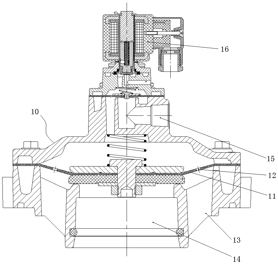
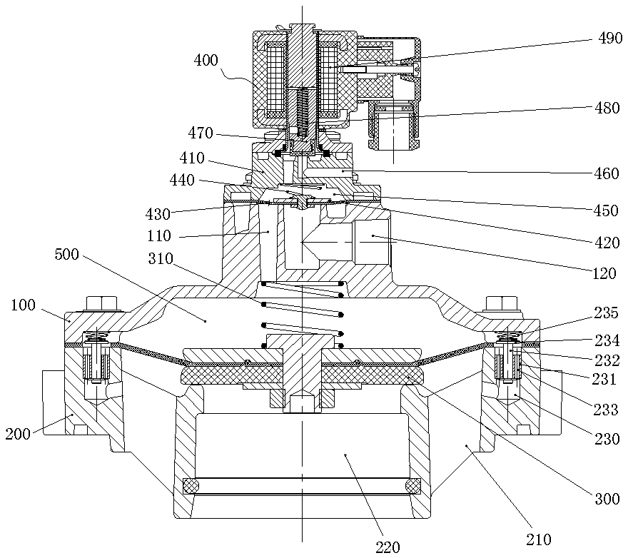
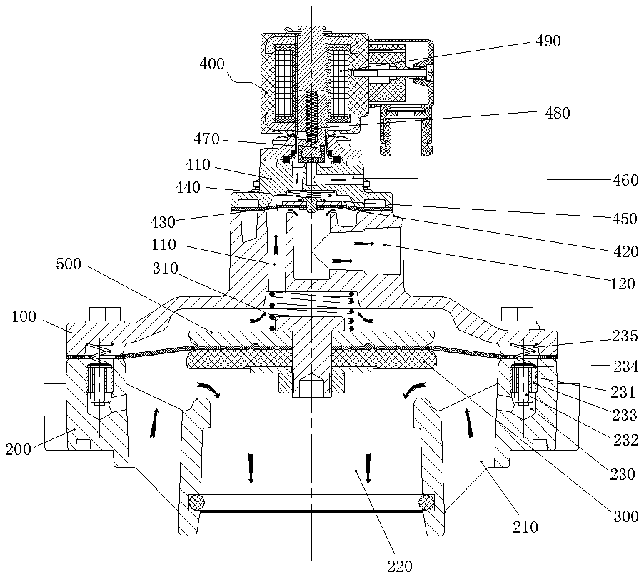
[0019] Such as Figure 2~6 As shown, a high-efficiency electromagnetic pulse valve includes an upper valve seat 100 and a lower valve seat 200, an inlet passage 210 is arranged on the edge of the lower valve seat 200, an air outlet passage 220 is arranged at the center of the lower valve seat 200, and an air outlet passage 220 is arranged on the upper valve seat 100 and the lower valve seat 200. A first diaphragm assembly 300 is arranged between the lower valve seat 200 to block the inlet passage 210 and the outlet passage 220, a first spring 310 is arranged between the first diaphragm assembly 300 and the upper valve seat 100, and the upper valve The upper end of the seat 100 is also provided with a control valve 400 capable of attracting the first diaphragm assembly 300 to move upwards, and a first air chamber 500 is provided between the first diaphragm assembly 300 and the upper valve seat 100, which is characterized in that: the lower valve seat On 200, along the central a...


PUM


Abstract

The invention relates to an efficient electromagnetic pulse valve and a working method thereof. The efficient electromagnetic pulse valve comprises an upper valve seat and a lower valve seat, whereinan air inlet channel is formed in the edge of the lower valve seat, an air outlet channel is formed in the center of the lower valve seat, a first diaphragm assembly is arranged between the upper valve seat and the lower valve seat to partition the air inlet channel and the air outlet channel, a first air chamber is arranged between the first diaphragm assembly and the upper valve seat, a plurality of air channels used for enabling the air inlet channel to communicate with the first air chamber are formed in the lower valve seat along the central axis of the lower valve seat in an array mode,mounting seats are arranged in the air channels, valve rods capable of moving axially relative to the mounting seats are arranged in the centers of the mounting seats in a penetrating mode, through holes enabling the upper sides and the lower sides of the mounting seats to communicate with each other are further formed in the mounting seats, valve bonnets used for sealing the upper ends of the through holes are arranged at the upper ends of the valve rods, and compression springs used for jacking the valve bonnets to be at the upper ends of the mounting seats are further arranged at the upperends of the valve bonnets. According to the efficient electromagnetic pulse valve and the working method thereof, a throttling hole does not need to be arranged on a valve diaphragm, so that the valveis prone to blockage during working, and the circulation efficiency of airflow is improved.

Description

technical field [0001] The invention relates to a high-efficiency electromagnetic pulse valve and its working method. Background technique [0002] The pulse valve refers to the diaphragm valve that is controlled by the pilot valve such as electromagnetic or pneumatic, and can open and close the high-pressure air source in an instant to generate pulses. The pulse valve is the main component of the bag filter. The existing pulse valve communicates with the upper and lower air chambers of the diaphragm by setting an orifice on the diaphragm. When working, when the electromagnetic coil of the control valve is energized, the armature assembly is lifted upward under the action of electromagnetic force, and the pressure is released. The hole is opened and the gas is discharged. Due to the throttling effect of the diaphragm orifice, the gas flow out of the pressure relief hole is greater than the gas flow of the gas flowing into the rear air chamber through the orifice, so that the...

Claims


Application Information

Patent Timeline
Patent Type & Authority Applications(China)
IPC IPC(8): F16K31/365F16K31/06F16K7/12
CPCF16K7/12F16K31/0655F16K31/1262F16K31/365
Inventor 王金水
Owner 王金水
Why Eureka
Try Eureka