Master cylinder, especially for clutch or brake actuation of a motor vehicle

An operating device and active cylinder technology, applied in non-mechanical drive clutches, fluid drive clutches, hydraulic brake transmissions, etc., can solve problems such as troublesome structural design, cracks, etc., and achieve the effect of prolonging life, vibration and load impact attenuation

Active Publication Date: 2010-07-21
SCHAEFFLER TECH AG & CO KG
View PDF3 Cites 6 Cited by
  • Summary
  • Abstract
  • Description
  • Claims
  • Application Information

AI Technical Summary

Problems solved by technology

[0006] The structural design of the above solution is relatively cumbersome as multiple parts are required
In additi

Method used


Image

  • Master cylinder, especially for clutch or brake actuation of a motor vehicle
  • Master cylinder, especially for clutch or brake actuation of a motor vehicle
  • Master cylinder, especially for clutch or brake actuation of a motor vehicle

Examples


Embodiment Construction

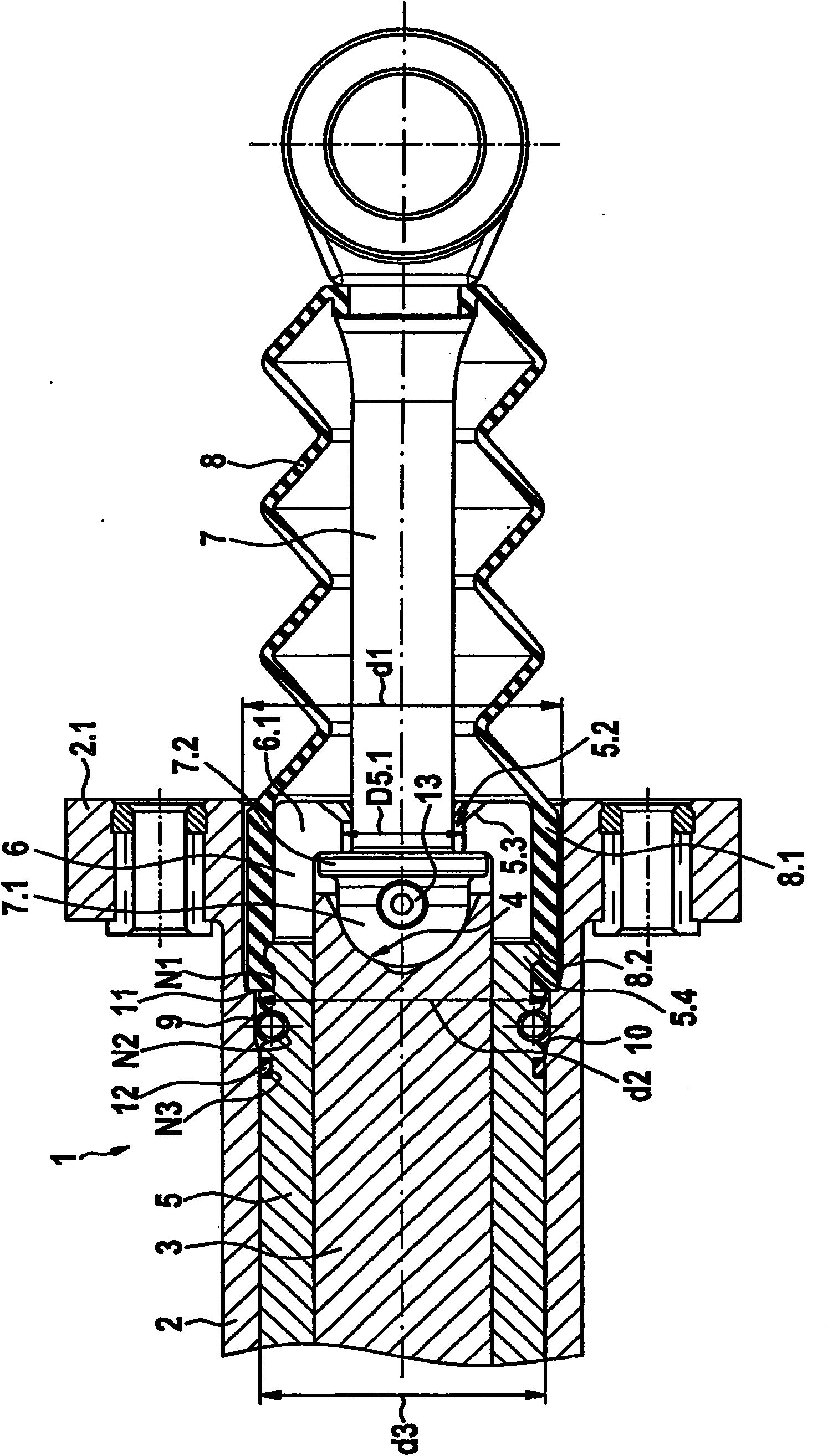
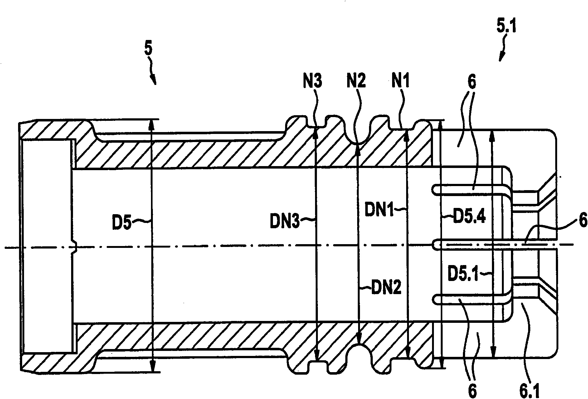
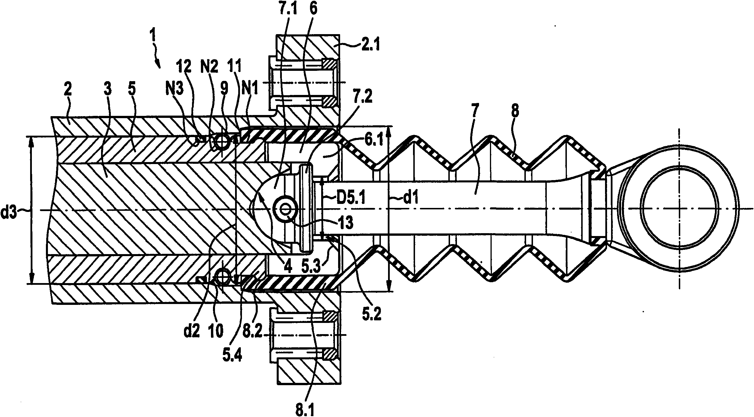
[0023] figure 1 shows a longitudinal section of the piston rod-side end of a master cylinder. figure 2 A detailed partial view of the intermediate sleeve is shown in longitudinal section. Master cylinder 1 has a guide sleeve 2 . In the guide sleeve 2 , a piston 3 with an end recess 4 is mounted axially displaceably in an intermediate sleeve 5 . Intermediate sleeve 5 according to figure 2 There is an end 5.1 provided with an axially extending slot 6. In addition, a radially inwardly directed flange 6.1 and a concentric mounting hole 5.2 are provided on the end 5.1 of the intermediate sleeve 5 . The mounting hole is extended outwards by a subsequent mounting ramp 5.3.

[0024] Adjacent to the end 5.1 of the intermediate sleeve 5 provided with the slot 6 in the outer contour of the intermediate sleeve 5 is a first groove N1, adjoining the first groove at a distance is a second groove N2 and Also adjoining this second groove at a distance is a third groove N3.

[0025] Th...


PUM


Abstract

The invention relates to a master cylinder, e.g. for the actuation of a clutch or a brake of a motor vehicle, wherein a piston is axially displaceable inside a guide sleeve and the piston has a front recess in which a piston-side end of a piston rod is received. The guide sleeve and the piston rod are sealed from each other by means of a sealing bellows. An intermediate sleeve is located between the guide sleeve and the piston, is actively connected to the guide sleeve and axially fixes the sealing bellows on its piston rod side end.

Description

technical field [0001] The invention relates to a master cylinder, in particular for a clutch or brake actuating device of a motor vehicle. Background technique [0002] Known from DE 195 23 215 B4 is a configuration of a piston for an active cylinder, wherein the piston consists of a piston skirt sleeve with a crown and two retaining shells arranged without play in the piston skirt sleeve, At the pedal-side end of the piston skirt sleeve, the holding shell has a ball-and-socket-shaped recess in which the ball head of the piston rod snaps in and is held in a non-positive manner. The piston rod can perform a pivoting movement through its fastening by means of a ball head. [0003] DE 199 60 335 A1 describes a master cylinder in which the piston also includes two retaining shells which are seated in a piston skirt sleeve. The holding shell here also forms a spherical segment-shaped recess for receiving the ball head of the piston rod. [0004] DE 10 2006 058 193 A1 describe...

Claims


Application Information

Patent Timeline
IPC IPC(8): F16D25/08F15B7/08B60T11/16
CPCF16D25/088B60T11/16F15B7/08F16D25/08F16D2025/081F16D2300/08
Inventor S·里贝罗R·弗兰卡
Owner SCHAEFFLER TECH AG & CO KG
Why Eureka
Try Eureka