Crane grider overturning and positioning device

A positioning device and crane technology, applied in the directions of auxiliary devices, auxiliary welding equipment, welding/cutting auxiliary equipment, etc., can solve the allowance for difficult-to-control movement of the crane, long workpiece and ground damage, and long workpiece impact. and other problems, to achieve the effect of convenient adjustment, improved work efficiency, and convenient welding position

Inactive Publication Date: 2010-07-28
叶宏洪
View PDF4 Cites 5 Cited by
  • Summary
  • Abstract
  • Description
  • Claims
  • Application Information

AI Technical Summary

Problems solved by technology

[0002]The main girder of a large crane is generally a long workpiece with a length of tens of meters. The long workpiece is composed of several flat plates welded. , the long workpiece must be lifted. The traditional solution is to manually turn the long workpiece by using a crane. This way of turning is inefficient, and because of its large size, it is difficult for a crane to control its movement. It is easy to cause the impact of the long workpiece on the ground, thus causing damage to the long workpiece and the ground

Method used


Image

  • Crane grider overturning and positioning device
  • Crane grider overturning and positioning device
  • Crane grider overturning and positioning device

Examples


Embodiment Construction

[0018] The present invention will be further described below in conjunction with the accompanying drawings and embodiments.

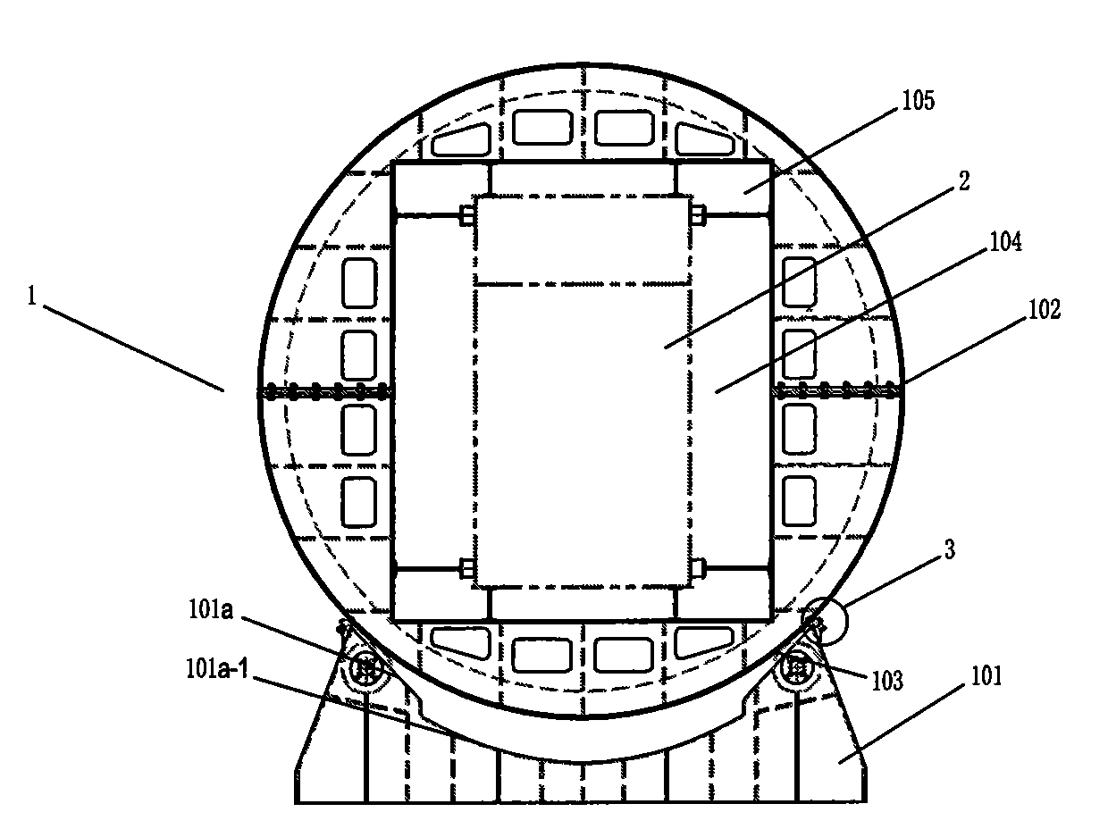
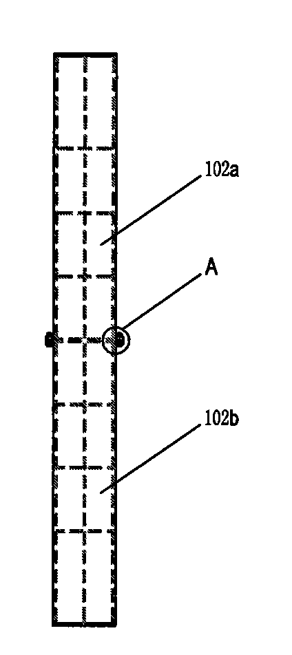
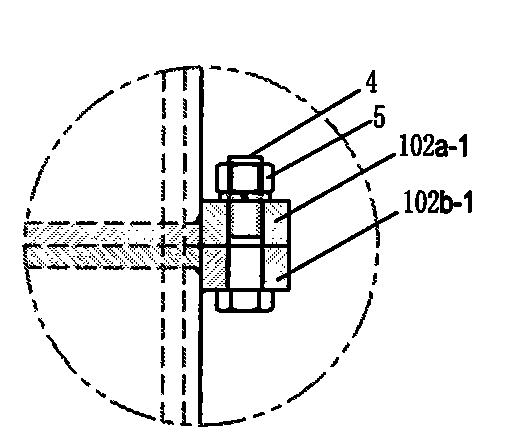
[0019] Such as Figure 1 to Figure 5 As shown, a crane girder overturning positioning device includes at least two overturning frames 1 arranged front and rear. There is a distance between each overturning frame 1 and they are on the same central axis. Each of the overturning frames 1 consists of The base 101, the circular turning body 102 and the roller 103 are composed. The roller 103 is rotatably installed on the left and right ends of the base 101. The circular turning body 102 sits on the base 101 and its arc end surface is offset against the roller 103. The circular overturning body 102 has a central axis hole 104 that is matched with the crane main beam 2. On the central axis hole 104, there are a number of pressing blocks 105 that compress the end face of the crane main beam 2 extending toward the central axis, corresponding to the circular over...


PUM


Abstract

The invention relates to a crane grider overturning and positioning device, which comprises at least two overturning stands which are arranged on the front and the back, wherein the interval is left between the overturning stands, and the intervals are on the same central axis; each overturning stand comprises a base, a round overturning body and rollers; the rollers are rotatably arranged on the left end and the right end of the base; the round overturning body is positioned on the base, the arc end face thereof abuts against the rollers, the round overturning body is provided with a central axle hole matched with the crane grider, and a plurality of pressing blocks for pressing the end face of the crane grider are extended in the direction towards the central axis on the central axle hole; and the two outsides of the base, which correspond to the round overturning body, are respectively provided with a locking mechanism capable of controlling the round overturning body. The invention has the beneficial effects that the device has simple and reasonable structure, reduces the overturning cost, improves the working efficiency and ensures the welding quality.

Description

technical field [0001] The invention relates to an overturning and positioning device for a main girder of a crane, in particular to an overturning and positioning device for a main girder of a crane with high overturning efficiency and low manufacturing cost. Background technique [0002] The main girder of a large crane is generally a long workpiece with a length of tens of meters. The long workpiece is composed of several flat plates welded. When the bottom of the long workpiece needs to be welded, the long workpiece must be lifted. The crane manually flips the long workpiece, which is inefficient, and because of its huge size, it is difficult for the crane to control its moving margin, which may easily cause the long workpiece to hit the ground, thus Causes damage to elongated workpieces and the ground. Contents of the invention [0003] The object of the present invention is to solve the above-mentioned deficiencies in the prior art, and provide a crane girder overtu...

Claims


Application Information

Patent Timeline
IPC IPC(8): B23K37/047
Inventor 叶宏洪莫益来
Owner 叶宏洪
Why Eureka
Try Eureka