

Fin for heat exchanger and heat exchanger with fin
A technology of heat exchangers and fins, which is applied in the field of heat exchangers, can solve the problems of heat exchanger fin air volume reduction, affecting the performance of heat exchangers, etc., and achieve the effect of improving heat exchange performance and reducing water accumulation
- Summary
- Abstract
- Description
- Claims
- Application Information
AI Technical Summary
Problems solved by technology
Method used
Image

Examples
Embodiment 1
[0029] Figure 4(a) is a schematic view of a fin 1 according to an embodiment of the present invention. Fig. 4(b) is a cross-sectional view taken along the line IV-IV in Fig. 4(a). As shown in FIGS. 4( a ) and 4 ( b ), a fin 1 for a heat exchanger according to an embodiment of the present invention includes a circular arc segment 11 , a straight segment 12 , and a louver 15 . The shutter 15 includes a louver 19 .
[0030] As shown in Figures 4(a) and 4(b), the fin inclination angle of the fin 1 for heat exchanger according to the present invention (ie, the angle between the straight section of the fin and the horizontal plane) b, the circular arc The radius R of the segment 11, the fin pitch (that is, roughly the distance between the centers of adjacent arc segments) P, the center angle c of the arc segment 11, and the fin height H_Fin satisfy the following geometric relationship:
[0031] tan b = P 2 ...
Embodiment 2
[0045] As shown in Fig. 4(b), the accumulation of water in the area 18 between the fenestration sheets 19 is mainly caused by the surface tension of the water between the adjacent fenestration sheets 19. The surface tension formula of the water between the fenestration sheets is as follows The formula for the surface tension of water between fins, if the fenestration distance (that is, the minimum distance between the opposing surfaces of adjacent fenestrations) S can be increased, the surface tension of water between fenestrations can be reduced or eliminated , which can reduce or eliminate the accumulation of water between the windows. After calculating the window opening distance S=W_Louver×sin a≥0.4mm, the surface tension between the window opening sheets can be effectively weakened, where W_Louver is the window opening distance. W_Louver≥1mm can be selected, where a is the inclination angle of the window opening 19, as shown in FIG. 4(b).
[0046]As shown in Figure 4(a),...
Embodiment 3
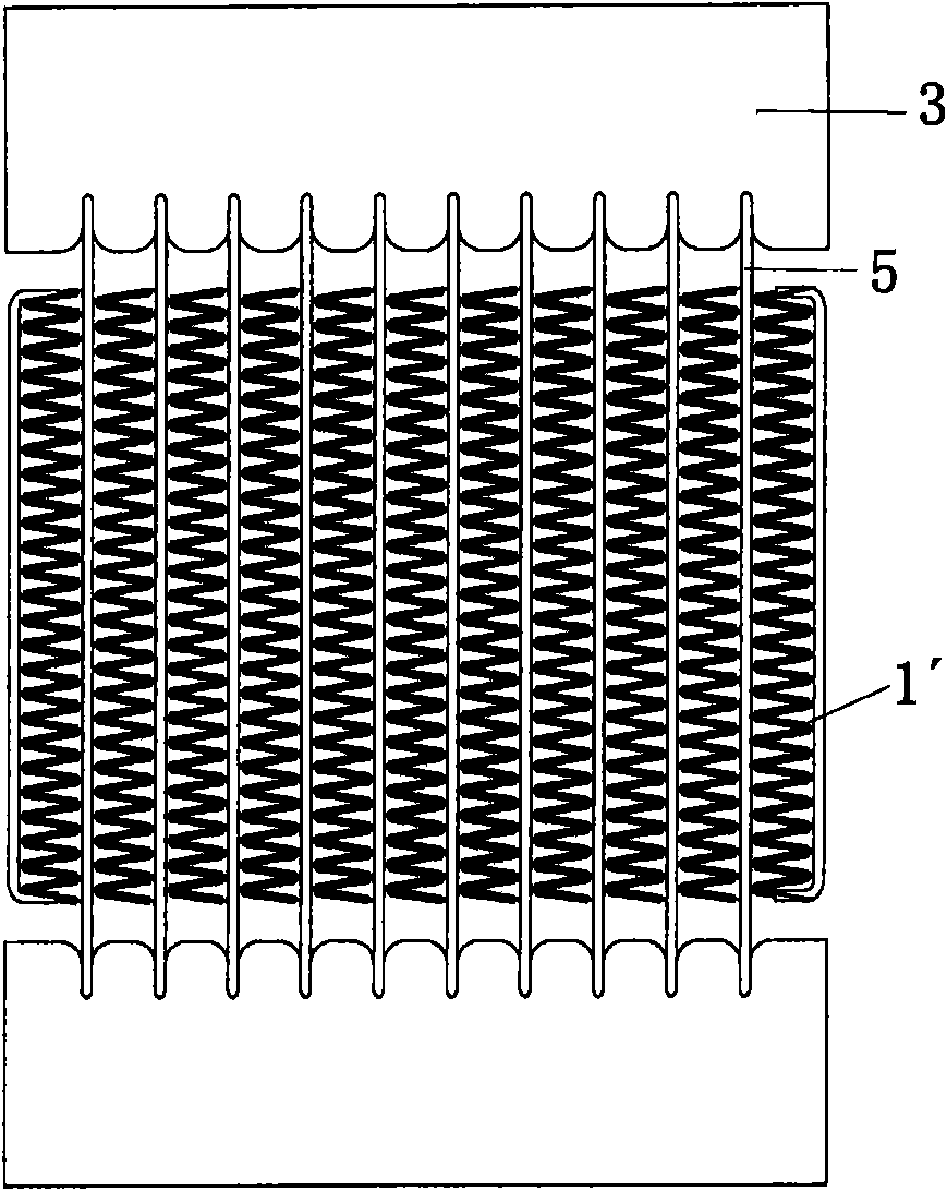
[0049] Figure 5 The state after the fin 1 according to the embodiment of the present invention is installed in the heat exchanger is shown. The radius R of the arc segment satisfies the relational expression 0.35mm Figure 5 As shown in , when the fins 1 are installed in the heat exchanger, a pressing force between the flat tubes 5 and the fins 1 can be made. The contact area between the fin and the flat tube is further increased, and at the same time, the heat exchange efficiency of the fin can be further improved, and the heat exchange performance can be further improved, and the increase of the R value reduces the water surface tension in the arc area, making it easier to drain. R>0.4mm after the sheet is compressed.
[0050] For each selectable range of parameters tan b, c, R, P, S, W_Louver, H_Louver / H_Fin, 2Rsin(c / 2), 2R(1-cos(c / 2)) in Examples 1-3, The parameters tan b, c, R, P, S, W_Louver, H_Louver / H_Fin, 2Rsin(c / 2), 2R(1-cos(c / 2)) can satisfy the above related rang...
PUM
 Abstract
Description
Claims
Application Information