Levelling staff capable of adjusting observation position and measurement technique thereof

A technology of leveling ruler and craftsmanship, applied in the field of surveying, can solve the problems of high cost of observation piers, unsatisfactory observation accuracy, unreachable sight line of leveling instruments, etc., and achieves the effects of increasing labor cost, reducing overall observation cost, and simple and convenient operation.

Active Publication Date: 2010-07-28
LUOYANG URBAN PLANNING & ARCHITECTURE DESIGN RES INST CO LTD
View PDF0 Cites 5 Cited by
  • Summary
  • Abstract
  • Description
  • Claims
  • Application Information

AI Technical Summary

Problems solved by technology

[0003] However, in special construction operations, such as the construction site floor is low, or the observation point is set at a high position, and the line of sight cannot reach the height of the observation point, the leveling staff cannot be read, and it is difficult to complete the normal leveling procedure.
[0004] There are two main ideas to solve the above problems: one is to raise the height of the level gauge, and the other is to lower the height of the level rod; however, in actual operation, there is no suitable implementation method for lowering the height of the level rod. like figure 1 As shown, the observation platform (4) and the observation pier (8) are set on the lower construction site of the floor, the level (6) is placed on the observation platform (4), and the observer (7) stands on the observation pier (8). ); however, the above method has the disadvantages of setting up the observation platform (4) and the observation pier (8) with high cost, prolonged operation time, and unsatisfactory observation accuracy, and the actual operation is very difficult, and it is not allowed to set up the observation platform in extreme operation occasions (4), observation pier (8); Therefore, it is necessary to explore a suitable implementation mode for reducing the height of the leveling rod

Method used


Image

  • Levelling staff capable of adjusting observation position and measurement technique thereof
  • Levelling staff capable of adjusting observation position and measurement technique thereof
  • Levelling staff capable of adjusting observation position and measurement technique thereof

Examples


Embodiment Construction

[0047] The present invention will be further explained below in conjunction with the accompanying drawings. It should be noted that the purpose of disclosing the present invention is to protect all changes and improvements of the present invention. As long as the technical scheme of changing and adjusting the position of the leveling rod through the auxiliary device is included in the scope of the present invention within the scope of protection.

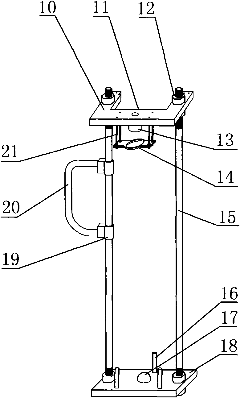
[0048] figure 2 Among them, the auxiliary sleeve includes an upper plate 10, a vertical rod 15, and a lower plate 18. The vertical rod 15 is a screw structure with threads at both ends. The nuts 12 on the top and bottom of the disc 10 and the lower disc 18 tighten the vertical rod 15, and the vertical relationship between the upper and lower discs and the vertical rod 15 can be adjusted by adjusting the screwing distance between the nut 12 and the vertical rod 15, and the distance between the upper and lower discs can be adjusted. ...


PUM


Abstract

The invention discloses a levelling staff capable of adjusting the observation position, which comprises the body of the levelling staff (1) and an auxiliary holding rod, the auxiliary holding rod comprises an upper plate (10), a lower plate (18) and upright rods (15), the upright rods are connected between the upper plate and the lower plate and limit the upper plate and the lower plate, the upper plate is provided with a notch (11), and the lower end surface of the upper plate is provided with an upper contact (13); a lower contact (17) is arranged at the center of the upper end surface of the lower plate, and staff retainers (16) are also arranged around the lower contact on the upper end surface of the lower plate. The invention also discloses a technique using the levelling staff to carry out measurement, which includes steps such as checking the auxiliary holding rod, mounting the levelling staff on the auxiliary holding rod, placing the auxiliary holding rod, measuring, determining the additive constant of the holding rod and processing data. When the position of an observation point is higher than the sight line of a level, the height of the levelling staff can be reduced, and thereby the overall observation cost of a special operation situation is reduced.

Description

technical field [0001] The invention relates to the technical field of measurement, in particular to a leveling staff with adjustable observation position and a measurement process thereof used in the settlement observation of buildings or structures. Background technique [0002] In existing construction occasions, when the leveling method is used to observe the settlement of buildings or structures, the leveling rod and the level are generally used in conjunction with the leveling rod, that is, the leveling rod is vertically erected on different observation points, and the leveling rod is used to read when the line of sight is horizontal. Take the marking value of the leveling staff, observe the leveling staffs at different observation points at the same station, and the difference between the readings of the leveling staffs at different observation points is the height difference between the two points; through the way of height difference transmission, the Known point el...

Claims


Application Information

Patent Timeline
Patent Type & Authority Applications(China)
IPC IPC(8): G01C5/00
Inventor 田海勇
Owner LUOYANG URBAN PLANNING & ARCHITECTURE DESIGN RES INST CO LTD
Why Eureka
Try Eureka