

Visual code transaction verification
a transaction verification and code technology, applied in the field of visual code transaction verification, can solve the problems of remote transaction verification, the signature system does not adapt to the modern remote electronic medium such as the internet, and the basic method of verification becomes increasingly invalid, so as to achieve easy transaction verification, low overhead processing, and high cryptographic strength
- Summary
- Abstract
- Description
- Claims
- Application Information
AI Technical Summary
Benefits of technology
Problems solved by technology
Method used
Image

Examples
Embodiment Construction
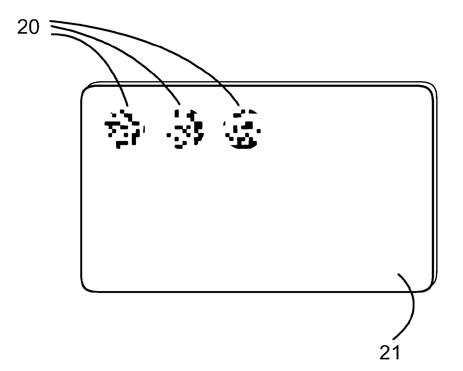
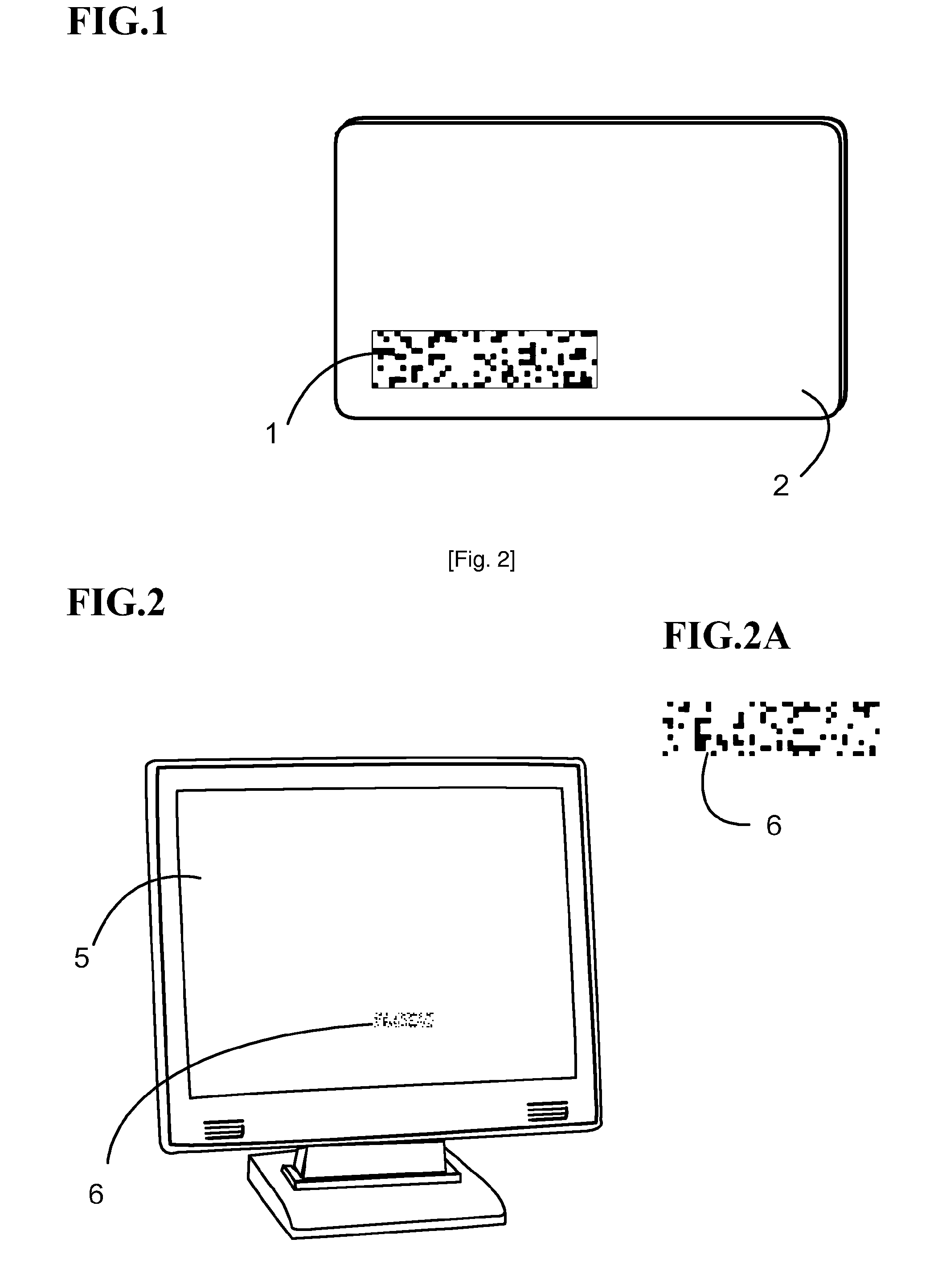
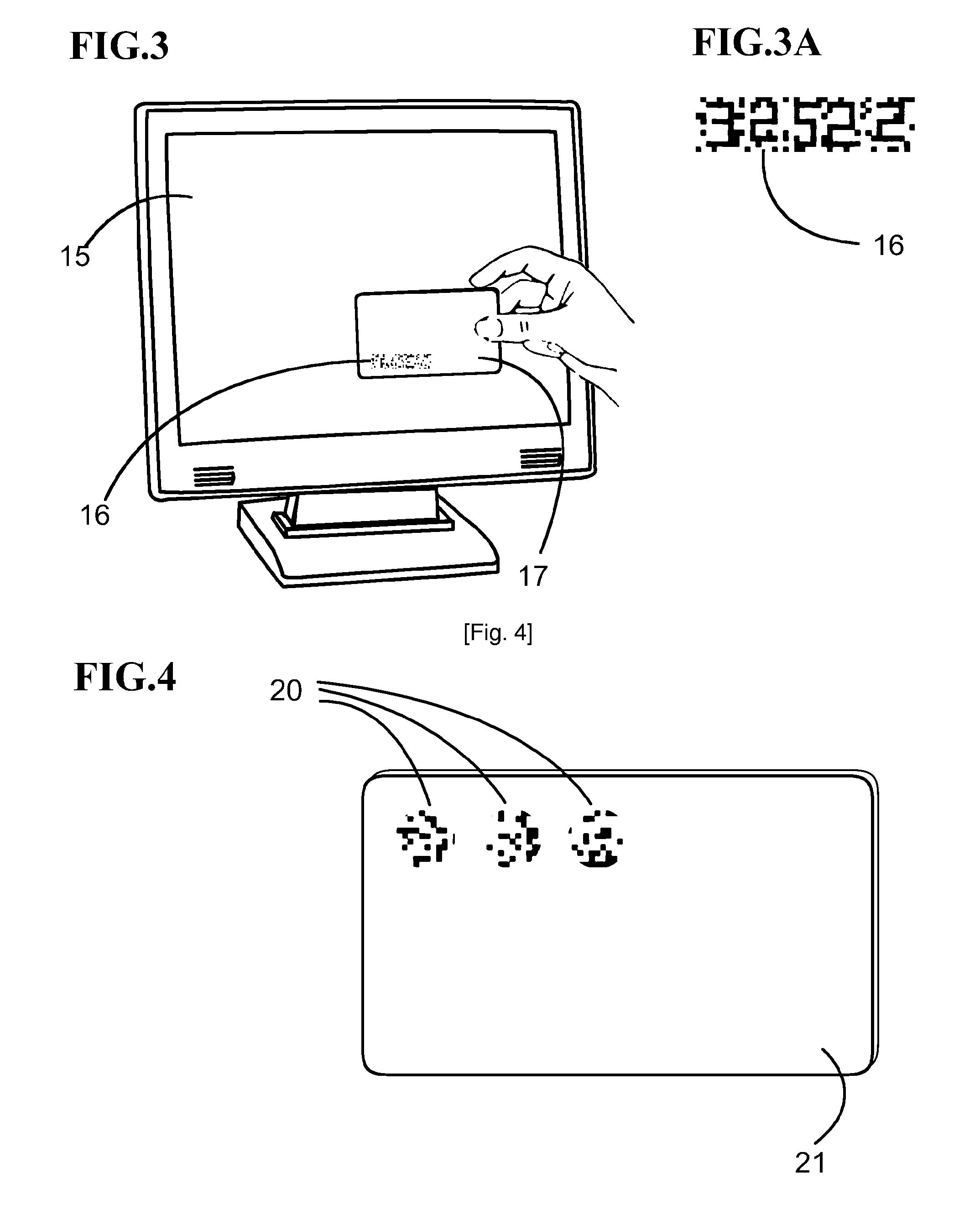
[0001]The present invention relates to a visual code transaction verification method. The method is enabled through a variety of different embodiments. One such embodiment being a standard plastic identification card or document with a recorded static optical pattern printed on a transparent section. Another potential embodiment is a version consisting of an electronic apparatus which consists of a digital transparent display connected to a processor which generates dynamic optical patterns using a cryptographic algorithm, synchronized with either a screen generated pattern image or another similar electronic apparatus, complete with its own electronic transparent display. This electronic apparatus would preferably take the form of a conventional membership card with added electronic functionality.
[0002]The user aligns the transparent pattern across a digital screen such as an internet connected computer screen or another electronic apparatus which displays a specific generated patt...
PUM
 Abstract
Description
Claims
Application Information