Decorative film and method for forming the same

a technology of decorative film and vapor deposition portion, which is applied in the direction of reradiation, instruments, transportation and packaging, etc., can solve the problems of increasing the risk of impairing the appearance of a preferred vehicle, difficult to form a vapor deposition portion and a non-vapor deposition portion, and not achieving good radiowave transmission/reception, etc., to achieve the effect of improving production yield, significantly reducing the formation cost and reducing the production tim

Inactive Publication Date: 2011-09-29
TOYOTA JIDOSHA KK
View PDF3 Cites 16 Cited by
  • Summary
  • Abstract
  • Description
  • Claims
  • Application Information

AI Technical Summary

Benefits of technology

[0029]As is understood based on the above descriptions, a decorative film can be formed by a very simple formation method according to the decorative film formation method of the present invention and a decorative film formed by the method. Therefore, formation cost can be significantly reduced and production time can be shortened, allowing the significant improvement of the production yield. In addition, a decorative film having a desirable metallic shine and a very low millimeter wave damping rate can be obtained.

Problems solved by technology

Accordingly, a radiowave transmitting and receiving apparatus, an engine room, and the like in a vehicle can be seen through the window portion, resulting in an increased risk of impairing a preferable vehicle appearance.
However, it is difficult to form a vapor deposition portion and a non-vapor deposition portion in a well-balanced manner.
For instance, when vapor deposition portions were formed very close to each other, good radiowave transmission / reception was not achieved.
Further, although an indium film is preferable as a film used for an emblem or the like because it exhibits a metal color, it is likely to be detached and thus has poor durability and abrasion resistance, which is disadvantageous.
In addition, since indium is a metal, it cannot be denied that there is a probability of erosion on an indium film.
However, such ceramic film comprising silicon dioxide or the like is colorless and therefore it cannot exhibit a good appearance in terms of a metal color or the like.
This is disadvantageous in terms of design.

Method used


Image

  • Decorative film and method for forming the same
  • Decorative film and method for forming the same
  • Decorative film and method for forming the same

Examples


Embodiment Construction

[0035]Embodiments of the present invention are described below with reference to the drawings. In addition, an embodiment in which an opaque resin layer is further formed on the surface of a decorative film formed on a resin substrate surface for color tone enhancement can be employed (not shown in the drawings).

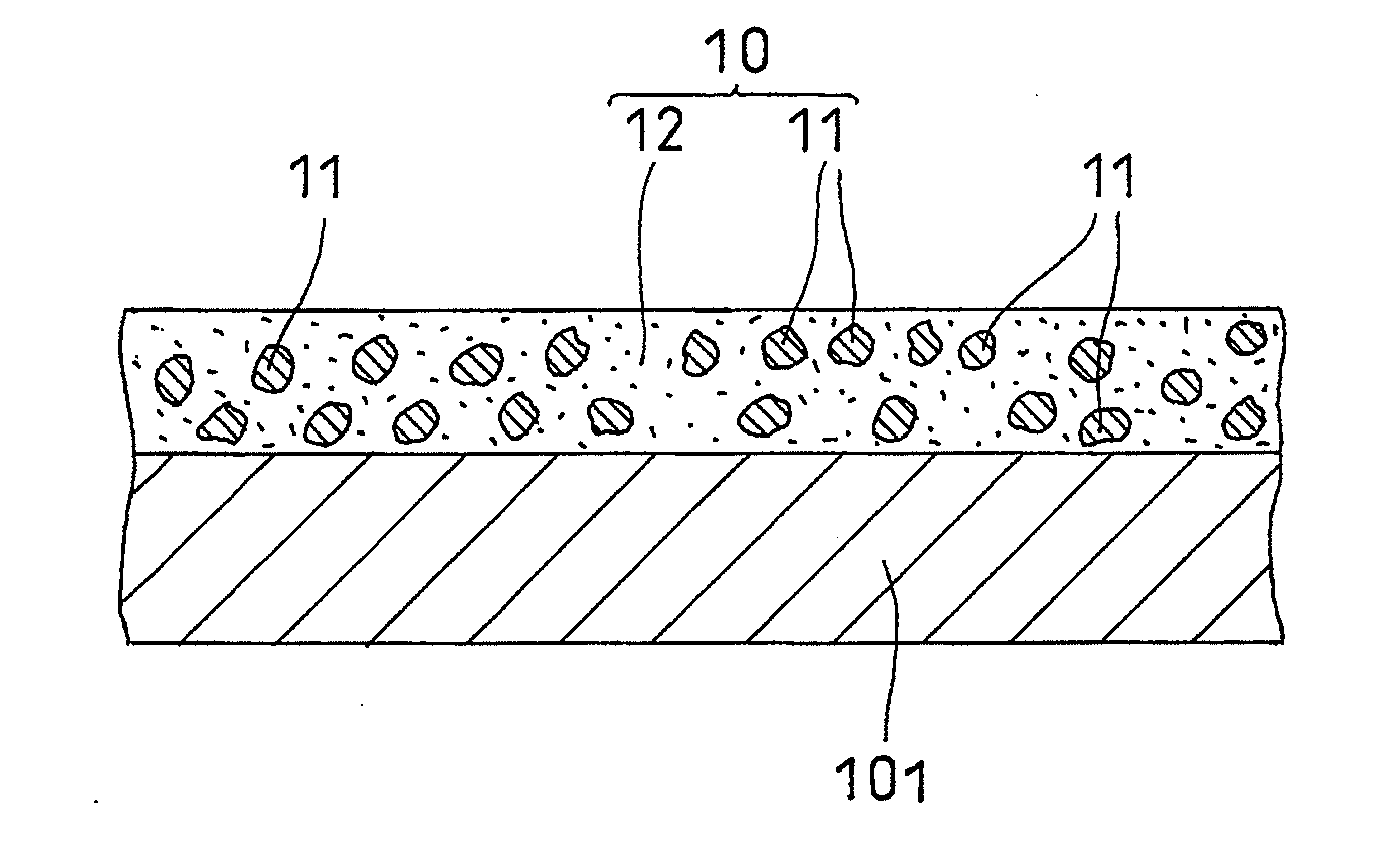
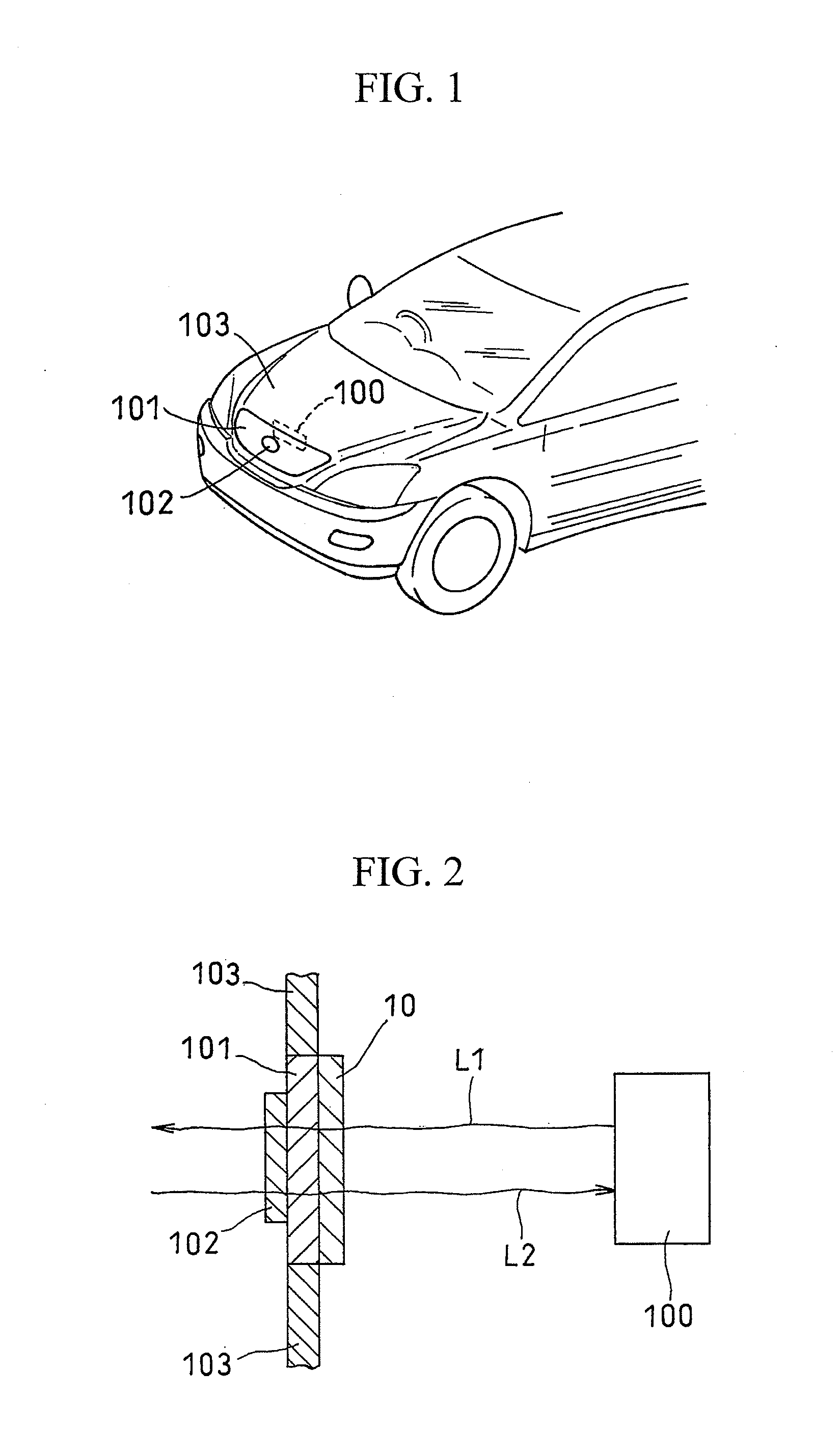
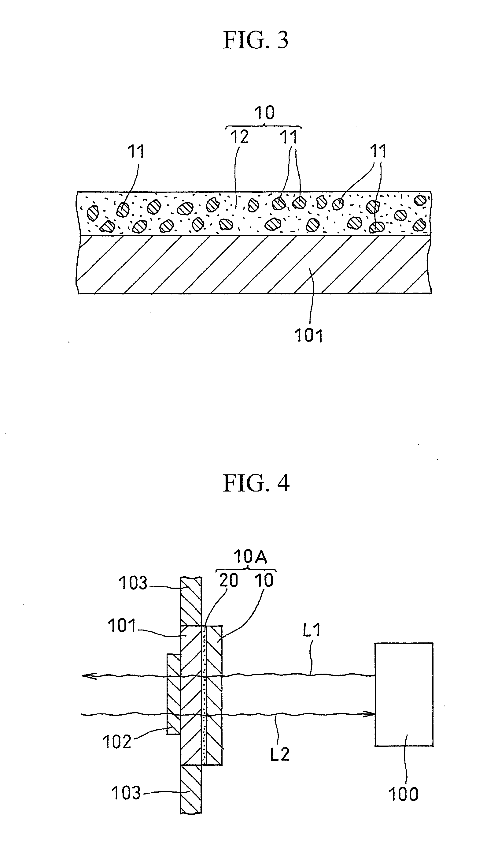
[0036]FIG. 1 schematically shows the relationship between a resin substrate composed of a front grille and an emblem positioned at the front part of a vehicle and a radar apparatus positioned behind the resin substrate within the vehicle. FIG. 2 shows a longitudinal section of a decorative film directly formed on a resin substrate in one embodiment of the present invention. The figure illustrates a situation in which a millimeter radiowave emitted from a radar apparatus is radiated forward through the resin substrate and then is reflected by an object in front of the radar apparatus so as to return to the radar apparatus through the resin substrate. FIG. 3 shows an enlarged ...


PUM

PropertyMeasurementUnit
particle sizeaaaaaaaaaa
thicknessaaaaaaaaaa
particle sizeaaaaaaaaaa

Abstract

The present invention relates to a decorative film formed on the surface of a resin substrate positioned within a radar device path and a method for forming the same. The present invention provides a decorative film that can be formed with high yield and efficiency without highly accurate film thickness regulation and is excellent in terms of radiowave transmission performance and appearance design, with a metallic color tone, and to provide a method for forming the same. Such method is a method for forming a decorative film 10 on the surface of a resin substrate 101 positioned within a radar device path, wherein a decorative film 10 comprising an organic film 12 in which metal nanoparticles 11 are dispersed is formed by producing an organic material comprising a solvent in which metal nanoparticles 11 (to which organic molecules are coordinated) are dispersed, applying the organic material to the surface of a resin substrate 101, and volatilizing the solvent.

Description

TECHNICAL FIELD[0001]The present invention relates to a decorative film formed on the surface of a resin substrate within a radar device path and a method for forming the same.BACKGROUND ART[0002]For antennas of communication equipments, radars, and the like used for radiowave transmission and reception, their functions are given priority. Therefore, the structure of an antenna body or the outer structure of an antenna is not limited in terms of design. For example, a rod antenna is used as a vehicle radio antenna in a manner such that the antenna structure can be seen from the outside of a vehicle. Depending on the position at which an antenna is installed, it is desirable that an antenna cannot be seen from the outside of a vehicle. For instance, a radar for determining the distance between a vehicle and an obstacle in front of the vehicle or the inter-vehicle distance between vehicles is preferably positioned at the center of a vehicle front portion such that it can exert its per...

Claims


Application Information

Patent Timeline
Patent Type & Authority Applications(United States)
IPC IPC(8): G01S7/02B32B5/16B05D5/00B82Y30/00C09D7/61
CPCB05D5/00B05D7/02C08K3/08Y10T428/25C09D7/1216G01S7/032H01Q1/44C08K9/04G01S7/03C09D7/61G01S2013/93271B60R13/00B60R19/52B05D7/24
Inventor YANAGIMOTO, HIROSHIBESSHO, TAKESHI
Owner TOYOTA JIDOSHA KK
Why Eureka
Try Eureka