Bionic synchronous signal lamp and control circuit thereof

A signal light control and synchronous signal technology, which is applied in the field of signal lights, can solve problems such as synchronization problems, electromagnetic interference, and poor fault tolerance, and achieve the effects of flexible installation, low cost, and reduced cost and difficulty

Inactive Publication Date: 2010-07-28
OCEANS KING LIGHTING SCI&TECH CO LTD +1
View PDF2 Cites 9 Cited by
  • Summary
  • Abstract
  • Description
  • Claims
  • Application Information

AI Technical Summary

Problems solved by technology

At present, the synchronous signal lights on the market mainly realize the transmission of synchronous signals through cables or radio broadcasting methods. The former is complicated in wiring and difficult in construction, while the latter will generate additional continuous radio signals and cause certain electromagnetic interference to the outside world.
[0003] In addition, there is another kind of synchronous signal light that adopts the "hand in hand" synchronization method. Although this synchronization method can save the centralized control box and the number of synchronously connected lights is not limited, this method has certain disadvantages, that is, when a lamp appears failure, there will be problems with the synchronization of all lights connected behind this light, less fault tolerance

Method used


Image

  • Bionic synchronous signal lamp and control circuit thereof
  • Bionic synchronous signal lamp and control circuit thereof
  • Bionic synchronous signal lamp and control circuit thereof

Examples


Embodiment Construction

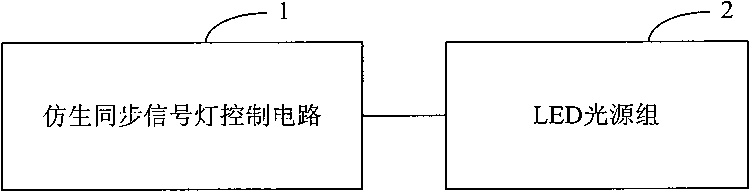
[0031] Such as figure 1 Shown is a structural block diagram of the bionic synchronous signal light of the present invention, the bionic synchronous signal light includes a bionic synchronous signal light control circuit 1 and an LED light source group 2 connected thereto, the bionic synchronous signal light control circuit 1 supplies power to the LED light source group 2, and controls the LED light source Multiple LED lights in group 2 are synchronized.

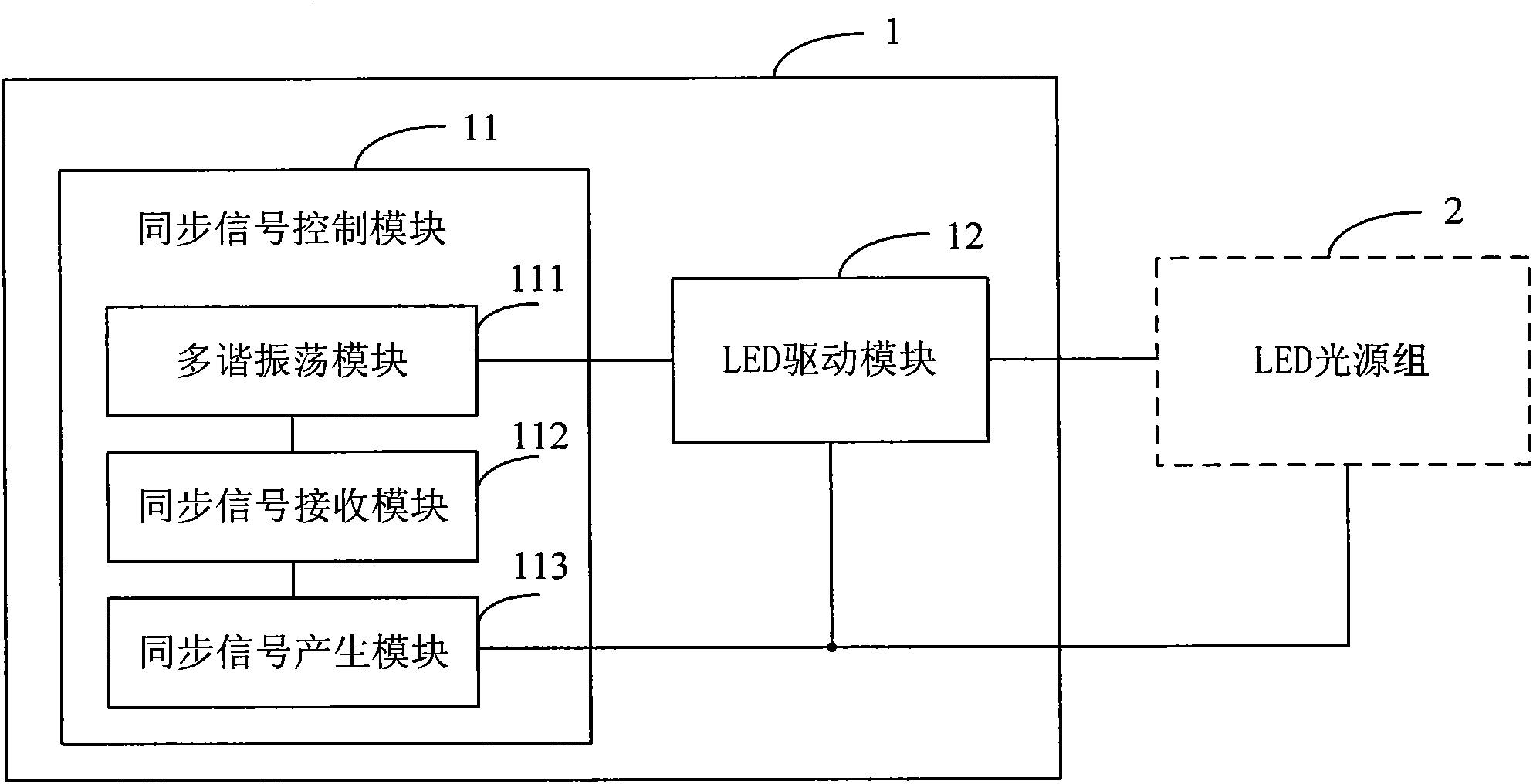
[0032] Such as figure 2 Shown is a structural block diagram of the bionic synchronous signal light control circuit of the present invention, the bionic synchronous signal light control circuit 1 includes a synchronous signal control module 11 and an LED driving module 12 .

[0033] Wherein, the synchronous signal control module 11 includes a multivibrator circuit 111 , a synchronous signal receiving module 112 and a synchronous signal generating module 113 . The synchronous signal generation module 113 is used for generati...


PUM


Abstract

The invention relates to a control circuit of a bionic synchronous signal lamp, which is connected with an LED light source group and comprises a synchronous signal control module and an LED driving module, wherein the synchronous signal control module comprises a synchronous signal generating module used for generating and transmitting an infrared synchronous signal, a synchronous signal receiving module used for receiving the infrared synchronous signal, a multivibrator circuit which is used for generating a PWM signal and adjusting the PWM signal according to the infrared synchronous signal; the PWM signal controls the LED driving module to supply power for the LED light source group in an intermittent way; and the synchronous signal generating module generates and transmits the infrared synchronous signal when the LED light source group lightens. The invention also relates to the bionic synchronous signal lamp which does not need a synchronous cable and other accessory equipment such as a centralized-control box and the like; the number of the bionic synchronous signal lamps is not limited; and the bionic synchronous signal lamp has better fault tolerance, no electromagnetic radiation pollution, low cost and flexible installation.

Description

technical field [0001] The invention relates to the technical field of signal lamps, and more specifically relates to a bionic synchronous signal lamp and a control circuit thereof. Background technique [0002] Today, synchronous signal lights have been widely used. For example, when a certain section of road fails temporarily, the synchronous signal light is used for fault identification. Generally, the synchronous signal of the synchronous signal light is a unified synchronous signal broadcasted by a host, and other synchronous signal lights receive this synchronous signal to flash, visually speaking, like a conductor leading a band. At present, synchronous signal lights on the market mainly realize the transmission of synchronous signals through cables or radio broadcasting methods. The former has complicated wiring and difficult construction, while the latter will generate additional continuous radio signals and cause certain electromagnetic interference to the outside ...

Claims


Application Information

Patent Timeline
Patent Type & Authority Applications(China)
IPC IPC(8): H05B37/02F21S2/00G08C23/04F21Y101/02
Inventor 周明杰李小虎
Owner OCEANS KING LIGHTING SCI&TECH CO LTD
Why Eureka
Try Eureka