Back conveying and bending mechanism of reinforcing steel bar automatic bending machine

A technology of bending mechanism and hoop bending machine, applied in the field of return bending mechanism, which can solve the problems of limited size of hoops, inability to quickly bend long hoops, and inability to fully meet the needs of production, etc.

Active Publication Date: 2010-08-04
TJK MACHINERY TIANJIN
View PDF0 Cites 11 Cited by
  • Summary
  • Abstract
  • Description
  • Claims
  • Application Information

AI Technical Summary

Problems solved by technology

Restricted by the processing technology, the size of the side of the hoop that can be bent by the automatic hoop bending machine of the prior art is limited, and the long hoop products with hooks at both ends cannot be quickly bent.
Some products cannot be automatically completed on the equipment at one time, and cannot fully meet the needs of production

Method used


Image

  • Back conveying and bending mechanism of reinforcing steel bar automatic bending machine
  • Back conveying and bending mechanism of reinforcing steel bar automatic bending machine
  • Back conveying and bending mechanism of reinforcing steel bar automatic bending machine

Examples


Embodiment Construction

[0015] Embodiments of the present invention will be further described below in conjunction with the accompanying drawings.

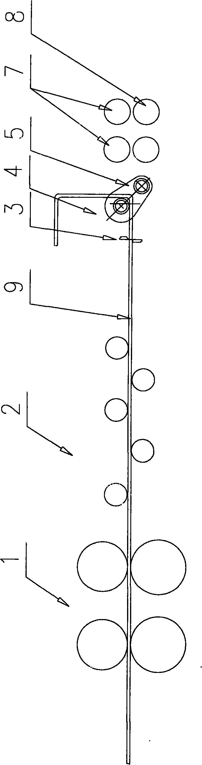
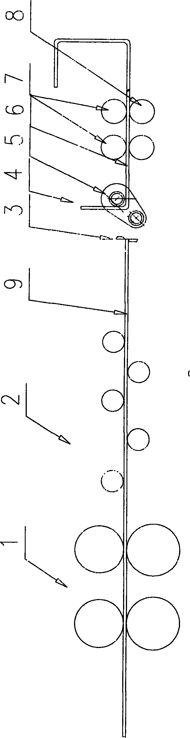
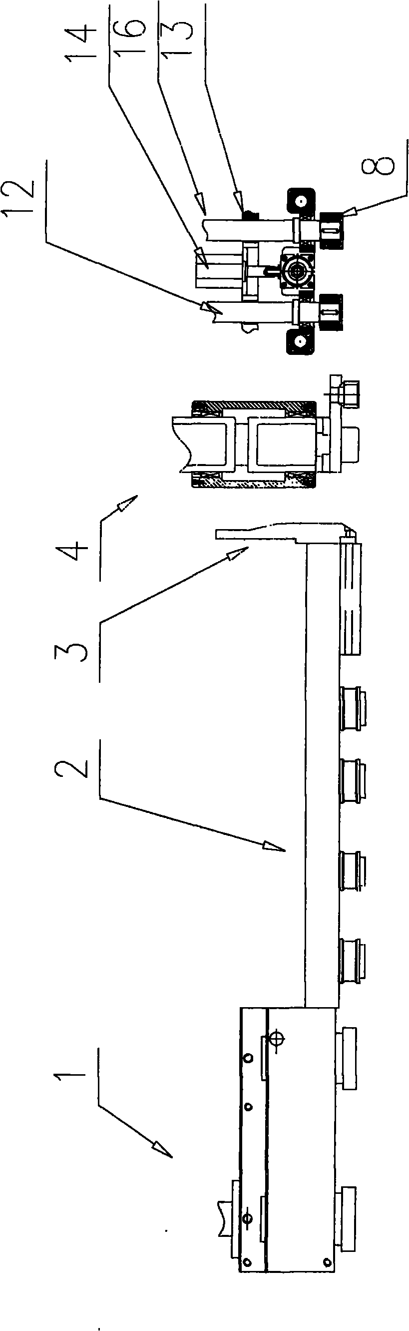
[0016] figure 1 It is a schematic front view of the structure of the present invention: figure 2 yes figure 1 After the steel bar is cut in the middle, the schematic diagram of the other end of the steel bar is bent after being sent back: image 3 yes figure 1 Schematic top view of the structure; Figure 4 yes figure 1 Schematic front view of the return mechanism; Figure 5 yes Figure 4 Sectional view of part 8 of middle return traction pulley; Figure 6 yes Figure 4 The top view of the 8 parts of the middle return traction wheel.

[0017] The invention provides a loopback bending mechanism of an automatic hoop bending machine for steel bars. The loopback bending mechanism is located behind the bending mechanism and the shearing mechanism, and its structure includes: loopback active pulley 8, loopback driven pulley 11, loopback pressure wheel...


PUM


Abstract

The invention relates to a back conveying and bending mechanism of a reinforcing steel bar automatic bending machine, which comprises a back conveying drive traction wheel, a back conveying driven traction wheel, a back conveying press wheel, a back conveying stand and a telescopic cylinder, wherein the back conveying stand is installed on a stand, and the upper part of the back conveying stand is provided with the back conveying press wheel which is connected with a back conveying press mechanism; the lower part of the back conveying stand is provided with a back conveying power shaft and a back conveying driven traction wheel shaft; the end parts of the back conveying power shaft and the back conveying driven traction wheel shaft are respectively provided with a back conveying traction wheel and the back conveying driven traction wheel which are positioned under the back conveying press wheel; the back conveying stand is connected to a telescopic unit; the back conveying power shaft is connected with a rotating drive unit; and a power transfer device is arranged between the back conveying power shaft and the back conveying driven traction wheel shaft. The invention expands the function of the bending machine and processes more stirrup products once; when the reinforcing steel bar rotates, the product does not rotate; and the bending machine not only bends a coil rod reinforcing steel bar, but also rapidly bends the stirrup product bent by a straight reinforcing steel bar commonly used by engineering.

Description

technical field [0001] The invention relates to an automatic steel bar hoop bending machine, in particular to a return bending mechanism of the steel bar automatic hoop bending machine. Background technique [0002] With the rapid development of economic construction, the automatic processing equipment for stirrups - the automatic bending machine for steel bars has been widely used. The prior art steel bar automatic hoop bending machine comprises several traditional mechanisms such as traction mechanism, straightening mechanism, bending mechanism and shearing mechanism. With the development of production, there are new requirements for the efficiency and size of curved steel products. [0003] The production process of the above-mentioned prior art hoop bending machine is: after all the bending angles are bent, a shearing action is performed to complete the processing of a stirrup product. Restricted by the processing technology, the size of the stirrup side that can be be...

Claims


Application Information

Patent Timeline
Patent Type & Authority Applications(China)
IPC IPC(8): B21F23/00B21F1/00
Inventor 陈振东
Owner TJK MACHINERY TIANJIN
Why Eureka
Try Eureka