Sucker type silicon slice taking mechanism

A sucker-type, silicon wafer technology, applied to conveyor objects, transportation and packaging, etc., can solve the problems of high labor intensity, low wafer removal efficiency, and high wafer damage rate, to reduce production costs, overcome manual operations, and improve The effect of taking slices

Active Publication Date: 2010-08-04
WUXI LEAD INTELLIGENT EQUIP CO LTD
View PDF6 Cites 52 Cited by
  • Summary
  • Abstract
  • Description
  • Claims
  • Application Information

AI Technical Summary

Benefits of technology

The technical effect described by this new technology makes it easier for workers to handle large amounts of wafer material without damaging them or causing other problems during their workday. It also ensures uniformity between each piece's size and orientation within certain limits while still being efficient at handling small quantities of materials.

Problems solved by technology

This technical problem addressed in this patented method for handling and moving individual silicone wafer (silane) fragments from their manufacturing step onto an endless conveyance system used during the production processes described earlier involves manually taking them off each other or placing these pieces into boxes before they can move around inside the machine. These operations may also lead to issues such as dropped ones causing damages due to bouncing over obstacles like pipes or machinery parts. Additionally, there could be variations where different sections have been arranged differently leading to nonuniformity within the final product's appearance.

Method used


Image

  • Sucker type silicon slice taking mechanism
  • Sucker type silicon slice taking mechanism
  • Sucker type silicon slice taking mechanism

Examples


Embodiment Construction

[0015] The present invention will be further described below in conjunction with specific drawings and embodiments.

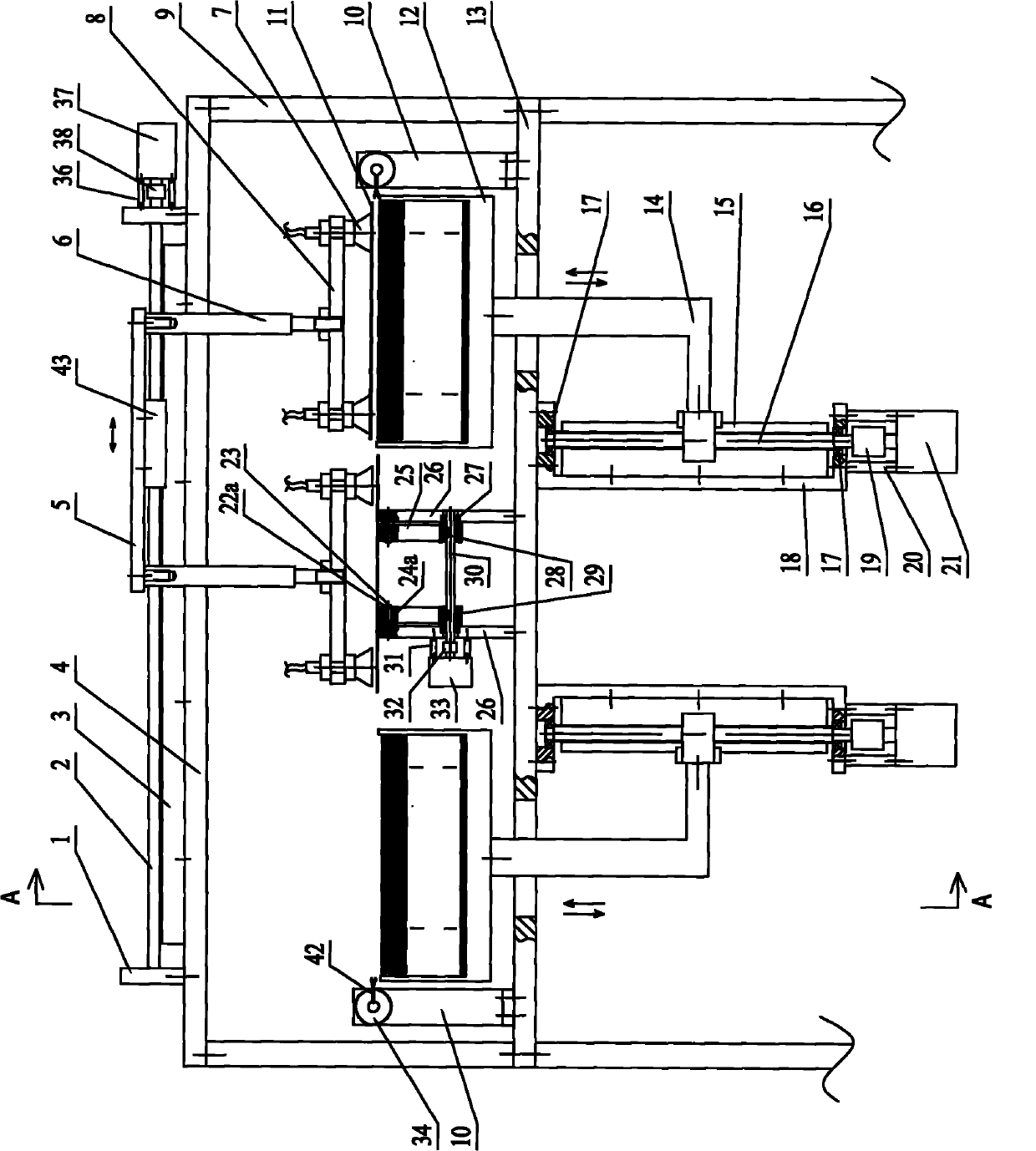
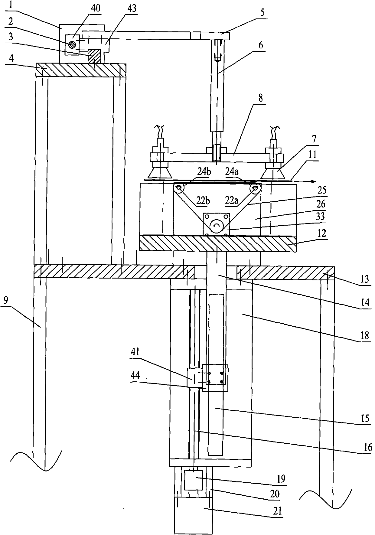
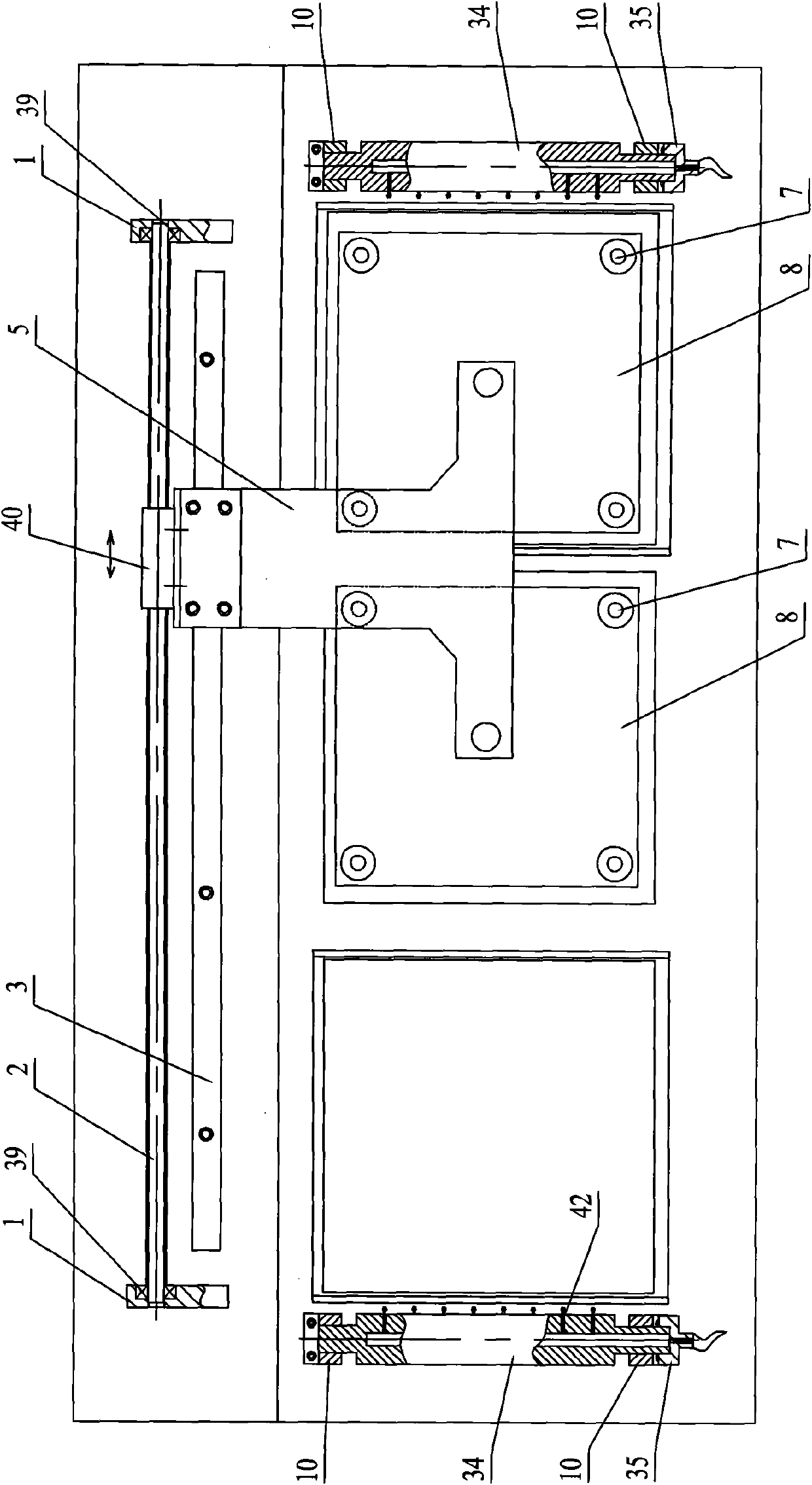
[0016] As shown in the figure, the present invention mainly consists of a frame 9 and a lifting device installed on the frame 9, a movable sucker device, an air injection device and a silicon wafer conveying device. The frame 9 is provided with an upper platen 4 and a lower platen 13; the lifting device is installed on the lower platen 13 of the frame 9, and the left and right sides of the lifting device each have one, which is used to lift the stacked silicon wafers 11 by a specified distance, so that Suction the silicon wafer 11 on the mobile suction cup device; the mobile suction cup device is installed on the upper platform 4, and the mobile suction cup device corresponds to the lifting device, and is used to alternately suck the silicon wafer 11 on the lifting device from left to right, and alternately place the silicon wafer 11 on the lifting device. The ...


PUM


Abstract

The invention relates to a sucker type silicon slice taking mechanism which comprises a stander, lifting devices installed on the stander, a movable sucker device and a silicon slice conveying device, wherein the stander is provided with an upper table plate and a lower table plate; the two lifting devices are installed on the lower table plate, are respectively arranged at left and right and are used for lifting overlapped silicon slices according to the specified distance; the movable sucker device is installed on the upper table plate, corresponds to the lifting device and is used for sucking the silicon slice on the lifting device left and right alternately and putting the silicon slices on the silicon slice conveying device alternately; and the silicon slice conveying device is arranged on the lower table plate, is positioned between the left and the right lifting devices, and is used for outputting the silicon slices sucked by the movable suction cup device. The sucker type silicon slice taking mechanism is simple in structure, ingenious and reasonable as well as high in degree of automation and silicon slice taking efficiency, can ensure the output silicon slices to have equal interval and same direction and to be arranged in sequence, and reduces the fault rate of the silicon slices.

Description


Claims


Application Information

Patent Timeline
Owner WUXI LEAD INTELLIGENT EQUIP CO LTD
Why Eureka
Try Eureka