Yarn processing method and spinning machine

A processing method and spinning machine technology, applied to spinning machines, free-end spinning machines, continuous winding spinning machines, etc., can solve the problems of insufficient detection precision and unstable quality

Active Publication Date: 2010-08-04
MURATA MASCH LTD
View PDF6 Cites 15 Cited by
  • Summary
  • Abstract
  • Description
  • Claims
  • Application Information

AI Technical Summary

Problems solved by technology

[0007] As mentioned above, there is a possibility that the accuracy of detection of yarn defects at the time of piecing becomes insufficient and unstable spun yarn is wound onto a package in a spinning machine without a delivery roller.

Method used


Image

  • Yarn processing method and spinning machine
  • Yarn processing method and spinning machine
  • Yarn processing method and spinning machine

Examples


Embodiment Construction

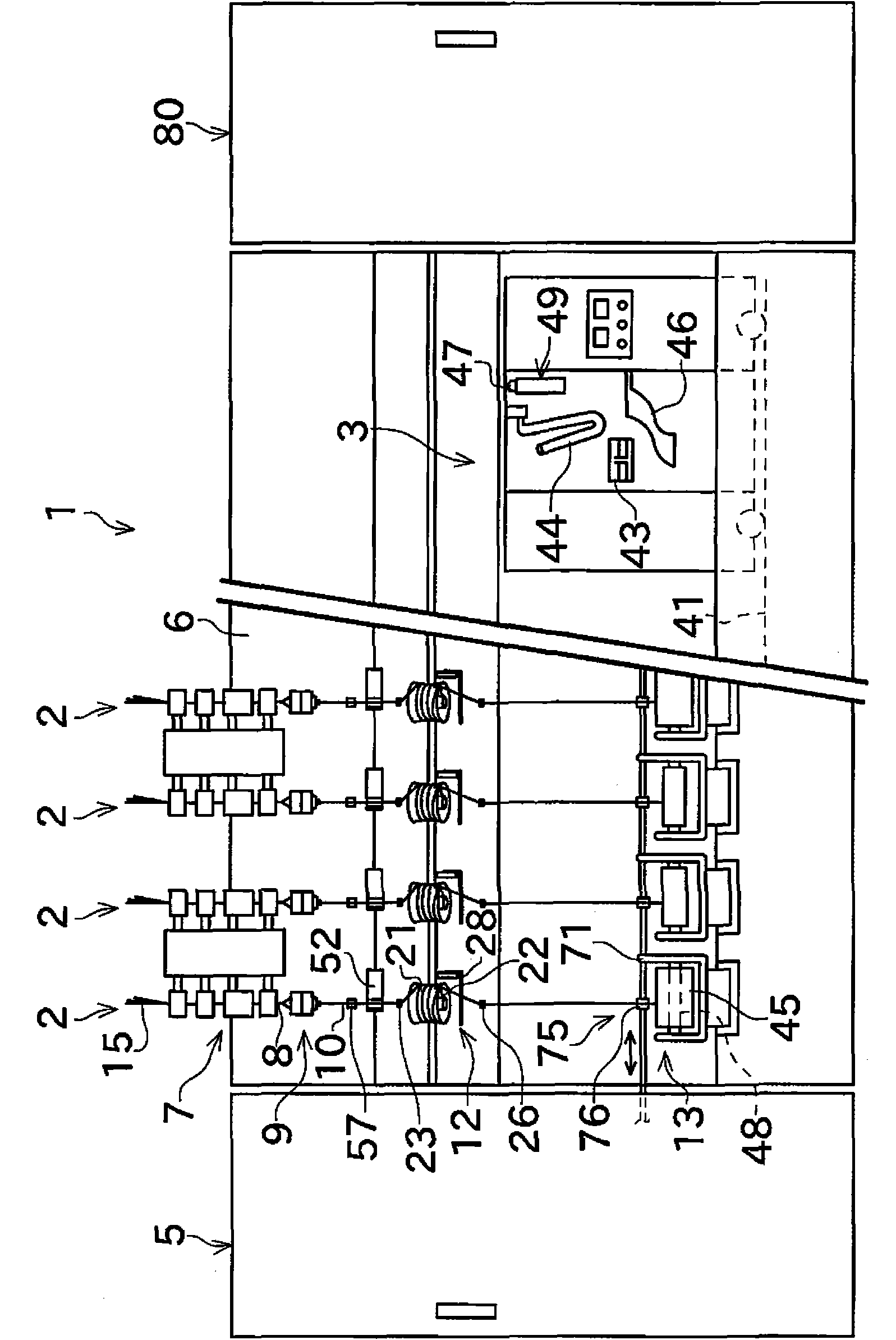
[0034] Next, a spinning machine (spinning machine) according to an embodiment of the present invention will be described with reference to the drawings. However, in this specification, "upstream" and "downstream" refer to upstream and downstream in the traveling direction of the yarn during spinning.

[0035] as figure 1 The spinning machine 1 of the illustrated spinning machine includes a plurality of spindles (spinning units 2 ) arranged in parallel. The spinning machine 1 includes a piecing cart 3 , a blower box 80 , and a prime mover box 5 .

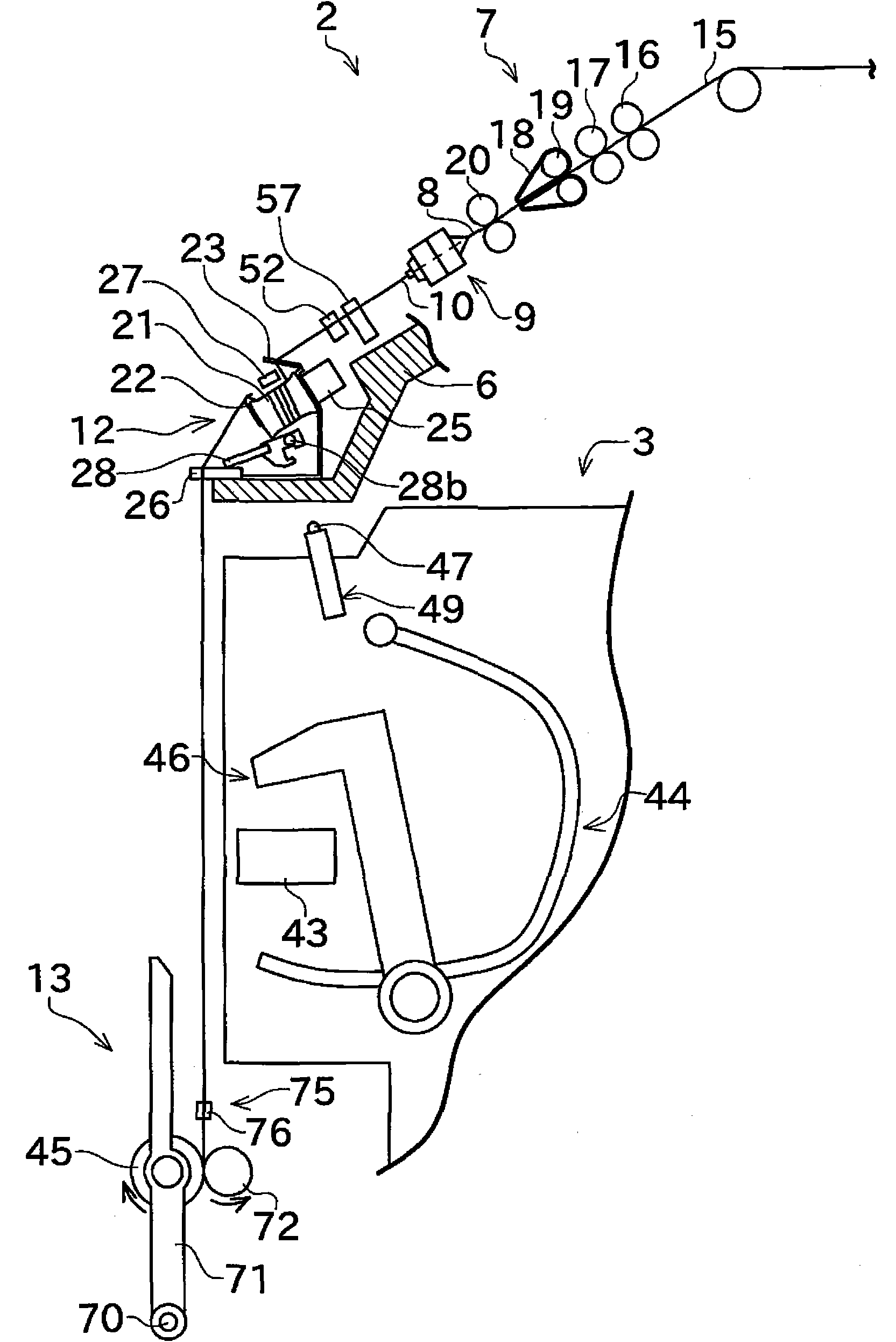
[0036] Such as figure 1 As shown, each spinning unit 2 includes a drawing device 7, a spinning device 9, a yarn accumulating device 12, and a winding device 13 as main components in this order from upstream to downstream. The pulling device 7 is provided near the upper end of the frame 6 included in the spinning machine 1 . The spinning device 9 spins the fiber bundle 8 sent from the drawing device 7 . The spun yarn 10 delivered...


PUM


Abstract

A spinning machine includes a spinning device, a winding device, a yarn accumulating roller, a yarn hooking member, and a yarn removing lever. The yarn accumulating roller winds spun yarn around an outer peripheral surface thereof and rotates with the spun yarn wound around to feed the spun yarn from the spinning device while applying tension to the spun yarn. While being engaged with the spun yarn, the yarn hooking member rotates integrally with the yarn accumulating roller, and thus prevents the spun yarn from being unwound from the outer peripheral surface of the yarn accumulating roller. The yarn removing lever is arranged downstream of the yarn hooking member in a yarn transporting direction, and can be moved between a lowered position where the yarn removing lever does not make contact with the spun yarn and a lifted position where the yarn hooking member makes contact with the spun yarn. At the lifted position, the yarn removing lever removes the spun yarn from the yarn hookingmember.

Description

technical field [0001] The invention relates to a yarn processing method and a spinning machine. More specifically, the present invention relates to a process for drawing out spun yarn from a spinning device using a yarn accumulating roller and a configuration for the process. Background technique [0002] Japanese Patent Application Laid-Open No. 2004-124333 discloses a spinning machine including a spinning device, a delivery roller, a yarn defect detection device, and a yarn storage device (yarn slack eliminating device). A nip roller (nip roller) is arranged to face the conveyance roller. The spun yarn is clamped between the delivery roller and the nip roller. The yarn is drawn out from the spinning device by applying tension to the downstream side in the yarn traveling direction to the nipped yarn by driving the conveying roller to rotate. The yarn accumulating device is arranged on the downstream side of the conveying roller, and includes a yarn accumulating roller (...

Claims


Application Information

Patent Timeline
Patent Type & Authority Applications(China)
IPC IPC(8): B65H51/22B65H57/00B65H63/00B65H67/08D01H13/00
CPCD01H9/08B65H51/22B65H2701/30D01H4/48D01H1/115D01H15/00
Inventor 冈正毅
Owner MURATA MASCH LTD
Why Eureka
Try Eureka