Metering method for saved illumination electricity

A measurement method and technology for lighting equipment, applied in the measurement of electrical variables, measuring devices, instruments, etc., can solve problems such as the inability to calculate the accurate power saving of energy-saving projects, the inability to implement lighting EPC projects, and the inability to obtain accurate lighting time, etc. Market prospect, simple structure, flexible effect

Inactive Publication Date: 2010-08-04
江苏宏康绿色技术服务有限公司
View PDF0 Cites 9 Cited by
  • Summary
  • Abstract
  • Description
  • Claims
  • Application Information

AI Technical Summary

Problems solved by technology

[0003] The technical problem to be solved by the present invention is to be able to overcome the most important parameter for implementing EPC business, the inability to obtain accurate lighting time due to the wide distribution of lighting fixtures in user units and frequent switching in the existing lighting EPC business model, It is also impossible to calculate the accurate energy saving of the energy-saving project, which leads to the difficulty that the lighting EPC project cannot be implemented. A measurement method for lighting energy saving is provided to enable the smooth implementation of energy management contract (EPC)

Method used


Image

  • Metering method for saved illumination electricity
  • Metering method for saved illumination electricity
  • Metering method for saved illumination electricity

Examples


Embodiment Construction

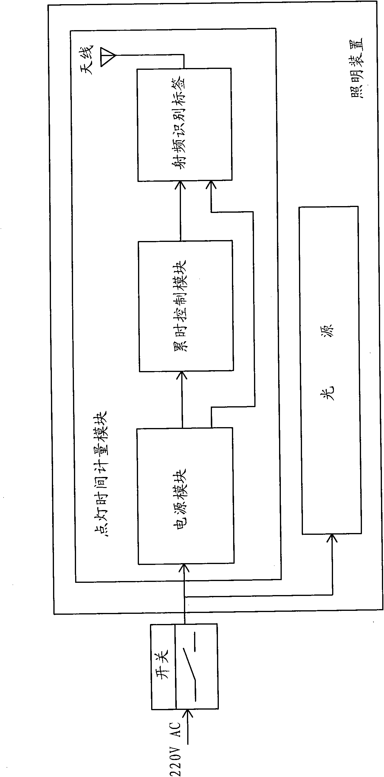
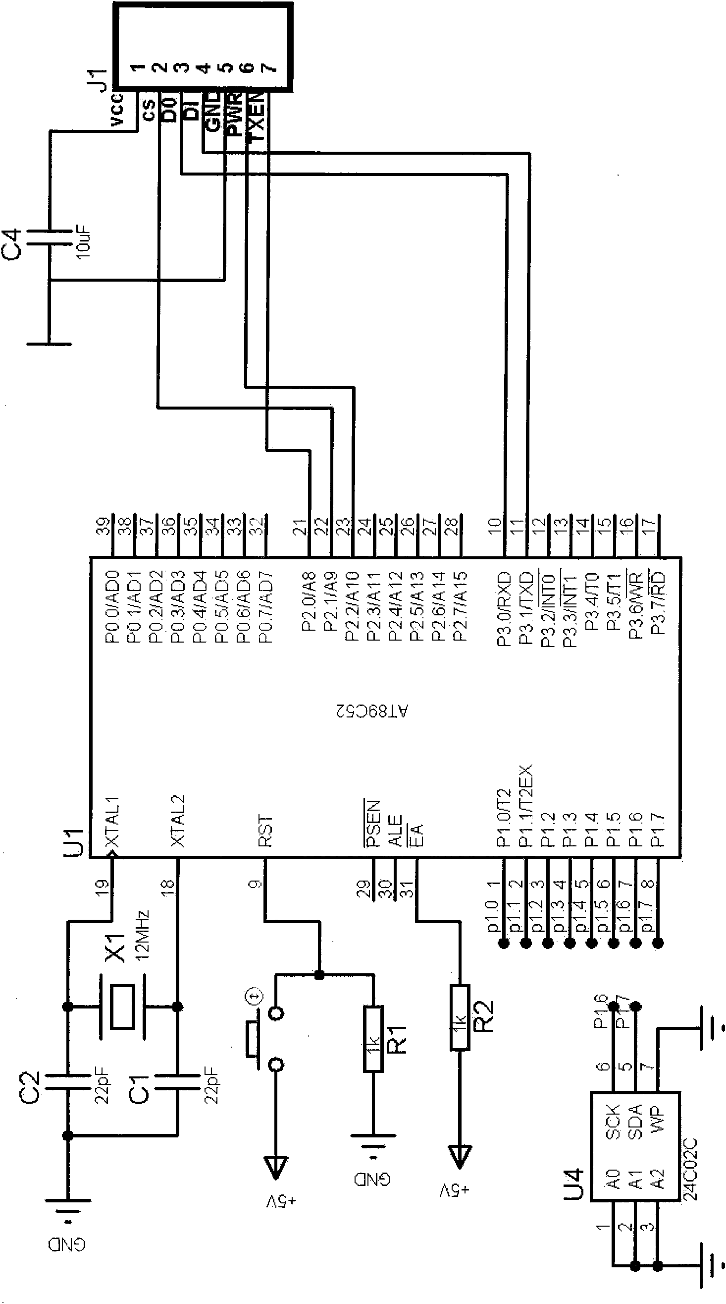
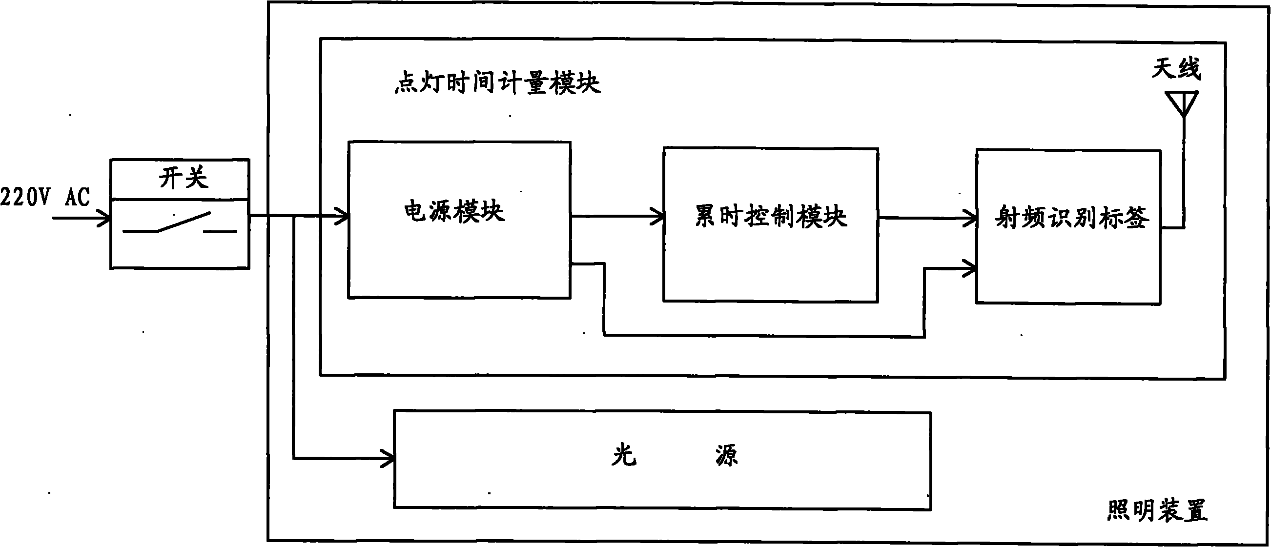
[0013] A measurement method for lighting energy saving in this embodiment, the hardware block diagram is as follows figure 1 As shown, the hardware electrical schematic diagram is shown in figure 2 As shown, the lamp contains a lighting time measurement module, and the lighting time measurement module includes: an accumulated time control module with an accumulated time timer, a radio frequency identification tag with a memory, and a power supply module. When the lamp is powered on, the accumulated time control module The accumulative timer in the timer starts accumulating time, and writes the timing data into the memory of the radio frequency identification tag. When the lamp is turned off, the timer stops timing. Continue timing, and the time data stored in the radio frequency identification tag is the lighting time of the corresponding lamp. The lamps described in this example are energy-saving lamps.

[0014] Specifically, in this embodiment, such as figure 2 As shown...


PUM


Abstract

The invention relates to a metering method for the working time of an illumination device. Each lamp comprises a cumulative time control module with a cumulative time timer, a radio frequency identification tag with a memory and a power supply module. When the lamp is powered on, the cumulative time timer in the cumulative time control module starts to time cumulative time and timing data is written into the memory of the radio frequency identification tag; and when the lamp is turned off, the timer stops timing and goes on timing on the basis of the timing data timed at the previous time after the lamp is powered on at the next time. Time data stored in the radio frequency identification tag is the lighting-on time of the corresponding lamp. A wireless code reader is used to read the lighting-on time information stored in the memory of the radio frequency identification tag, the information is input into a computer for data analysis, and the cumulative lighting-on time of the lamp after times of opening and closing within certain time period and the consumed electricity within the time period are obtained. In the invention, since the light-on time of each lamp is independently timed and the metering accuracy is high; and since the time data is 'downloaded' through a wireless way, the operation is convenient and the efficiency is high.

Description

technical field [0001] The invention relates to a measurement method for lighting energy saving, which is mainly used in the field of lighting energy management contract (EPC), and belongs to the technical field of energy saving measurement. Background technique [0002] At present, the main ways to achieve lighting energy saving are: 1. Users spend their own money to purchase energy-saving lamps to replace the original non-energy-saving lamps. Since users need to spend their own money, the lighting energy-saving initiative encouraged by the state is not easy to implement in the actual situation of users. Action support; 2. Through energy management contract (EPC), a new type of market-oriented energy-saving mechanism with zero risk and zero investment for users, the essence is that energy-saving service companies invest in energy-saving equipment for users, and use the energy costs saved in the future The energy-saving business method that pays the full cost of energy-savin...

Claims


Application Information

Patent Timeline
Patent Type & Authority Applications(China)
IPC IPC(8): G01R22/00
Inventor 张志军
Owner 江苏宏康绿色技术服务有限公司
Why Eureka
Try Eureka