
Cutting tool

A cutting tool and cutting body technology, applied in the direction of manufacturing tools, tool-workpiece connection, turning equipment, etc., can solve the problems of large structural space, weakening the tool matrix, etc., and achieve the effect of high functional safety

Inactive Publication Date: 2010-08-04
MAPAL FABRIK FUER PRAEZISIONSWERKZEUGE (DE)
View PDF0 Cites 9 Cited by
  • Summary
  • Abstract
  • Description
  • Claims
  • Application Information

AI Technical Summary

Problems solved by technology

It has been shown that the known adjustment devices require a relatively large installation space, which weakens the basic body of the tool

Method used


Image

  • Cutting tool
  • Cutting tool
  • Cutting tool

Examples


Embodiment Construction

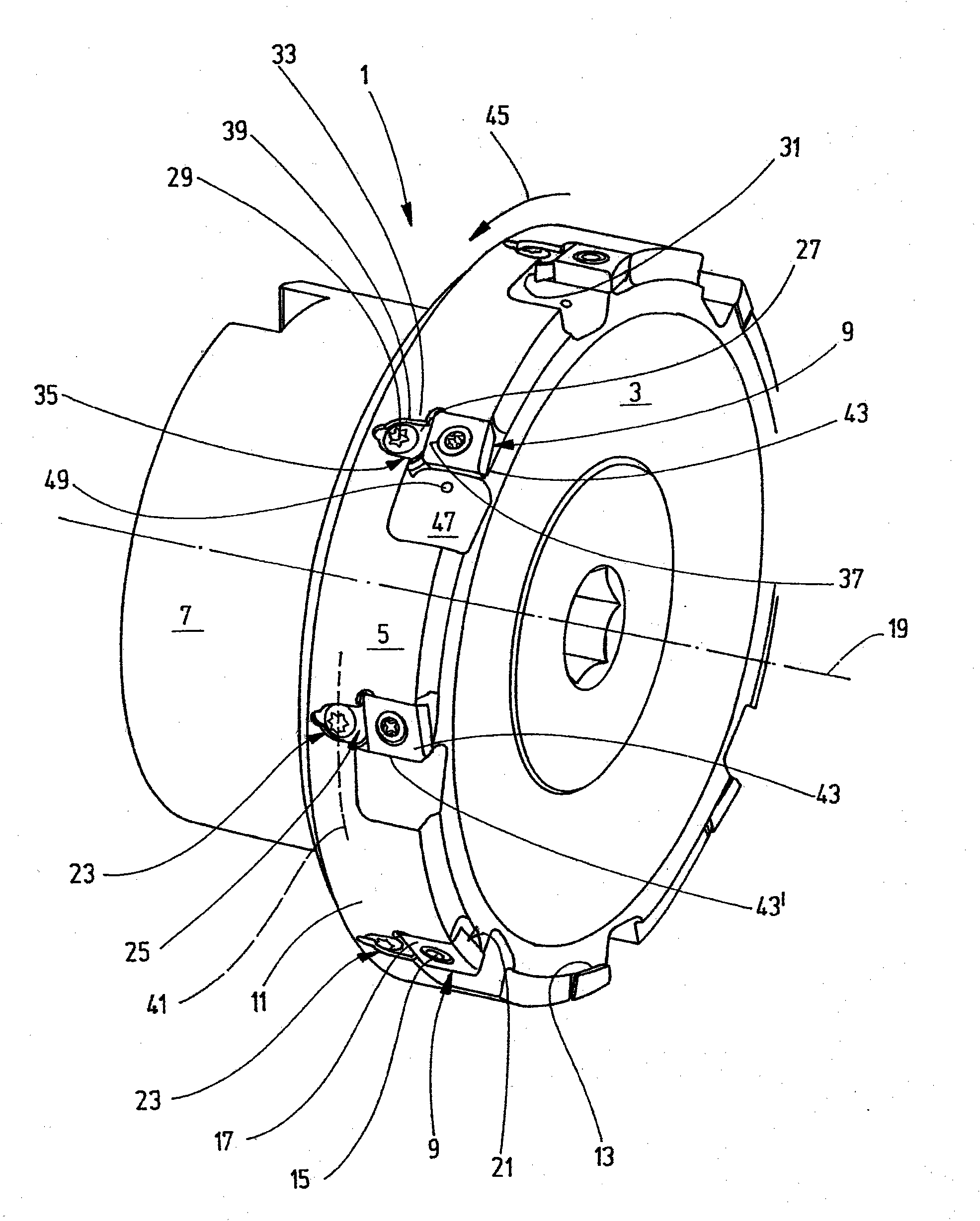
[0013] figure 1 The cutting tool 1 illustrated in is configured as a face milling cutter, for example. The cutting tool 1 is shown in a perspective view, so that, outside its circumferential surface, its front side is also visible. The cutting tool, referred to below simply as tool 1 , has a shank 7 for connecting the tool to the machine tool directly or via intermediate blocks, adapters or the like.

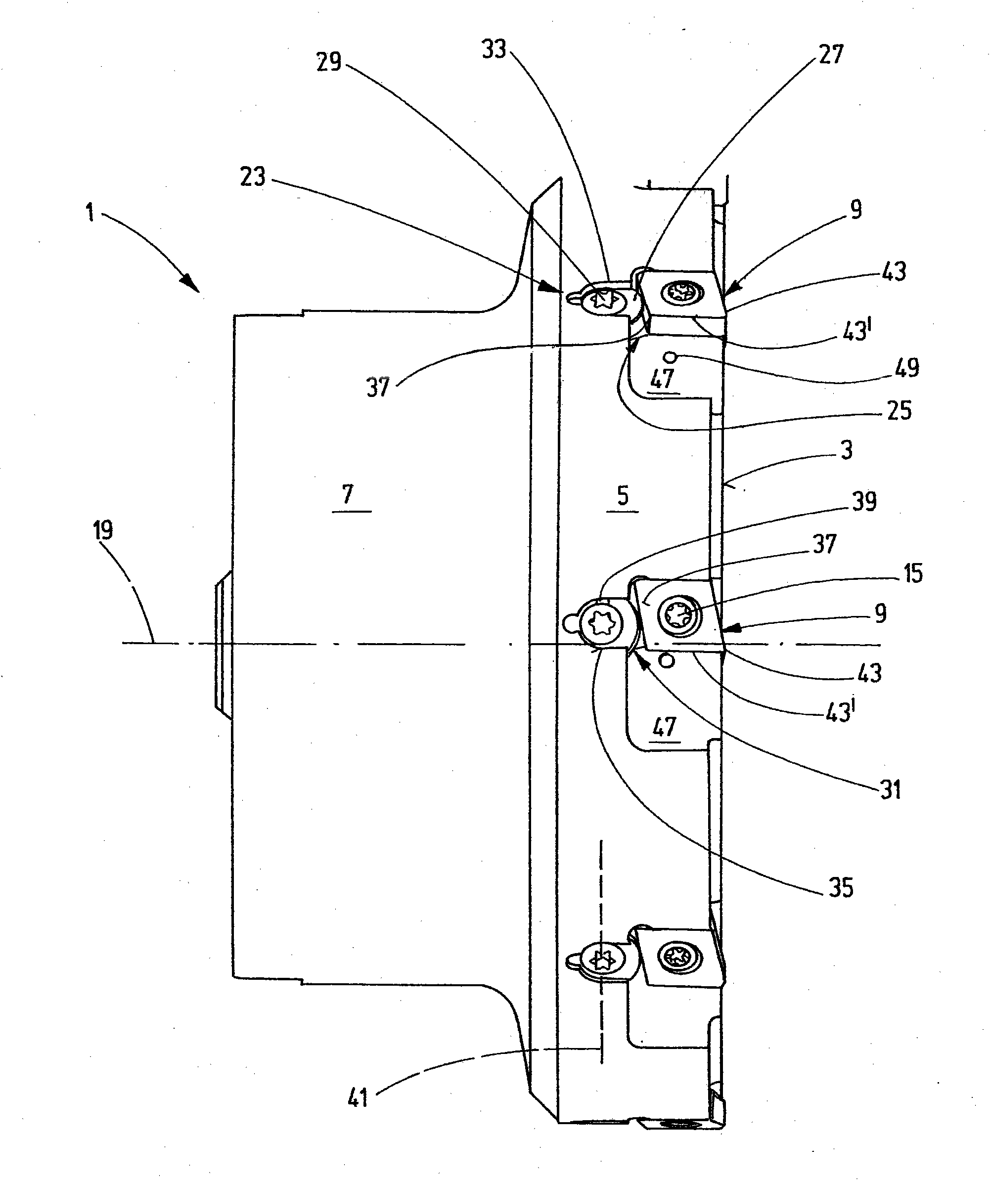
[0014] The tool 1 has at least one cutting body, here configured as a cutting disc 9 . The exemplary embodiment shown here provides eight such cutter heads 9 which are fastened to the base body 11 of the tool 1 . Here, the cutter head is mounted in the inclined recess 13 and fixed tangentially to the tool 1 by means of fastening screws 15 . The fastening screw 15 passes vertically through the cutter head. That is to say, the axis of rotation of the fastening screw 15 , not shown here, is perpendicular to the center axis 19 of the tool 1 , which also illustrates the axis of r...


PUM


Abstract

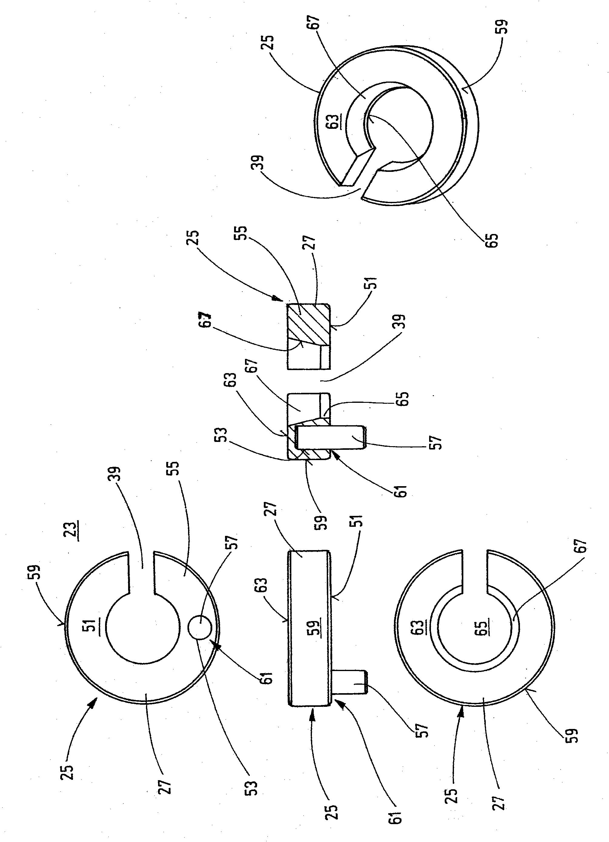
A cutting tool is proposed, comprising - a base body (11), - and at least one cutting body that can be attached to the base body (11), said body having - at least one geometrically defined blade (43), and having - an adjusting device (23) comprising an adjusting element (25) that can be expanded by means of an adjusting screw (29). The cutting tool is characterized in that the adjusting element (25) is configured as a slotted ring (27), which is supported both on the cutting body and on the base body (11) of the cutting tool (1).

Description

technical field [0001] The invention relates to a cutting tool according to the preamble of claim 1 . Background technique [0002] Cutting tools of the type described here are known. [0003] The cutting tool has a base body with at least one cutting body fastened thereto, which includes at least one geometrically defined tool. The adjustment device is used to be able to adjust the precise position of the tool. It has been found that the known adjustment devices require a relatively large installation space, which weakens the basic body of the tool. It is therefore the object of the present invention to provide a cutting tool which avoids this disadvantage and which has an adjustment device which requires little installation space. Contents of the invention [0004] To solve this object, a cutting tool is proposed which includes the features of claim 1 . The cutting tool comprises a base body, a cutting body with at least one geometrically defined tool, and an adjustm...

Claims


Application Information

Patent Timeline
Patent Type & Authority Applications(China)
IPC IPC(8): B23B27/16B23C5/24
CPCB23C5/2493B23C2240/24B23C5/2417B23C2265/08B23C2260/68B23C5/2462Y10T407/1922Y10T407/2242Y10T407/24B23C5/24B23C5/2234
Inventor 鲁道夫·斯特罗姆
Owner MAPAL FABRIK FUER PRAEZISIONSWERKZEUGE (DE)
Learn More