

Device for vacuum generation
A technology for generating device and vacuum, applied in valve devices, valve details, multi-port valves, etc., can solve problems such as failure, drop, pressure drop can no longer be compensated, etc., to prevent the decrease of vacuum degree and production work costs. Less, save the effect of compressed air
- Summary
- Abstract
- Description
- Claims
- Application Information
AI Technical Summary
Problems solved by technology
Method used
Image

Examples
Embodiment Construction
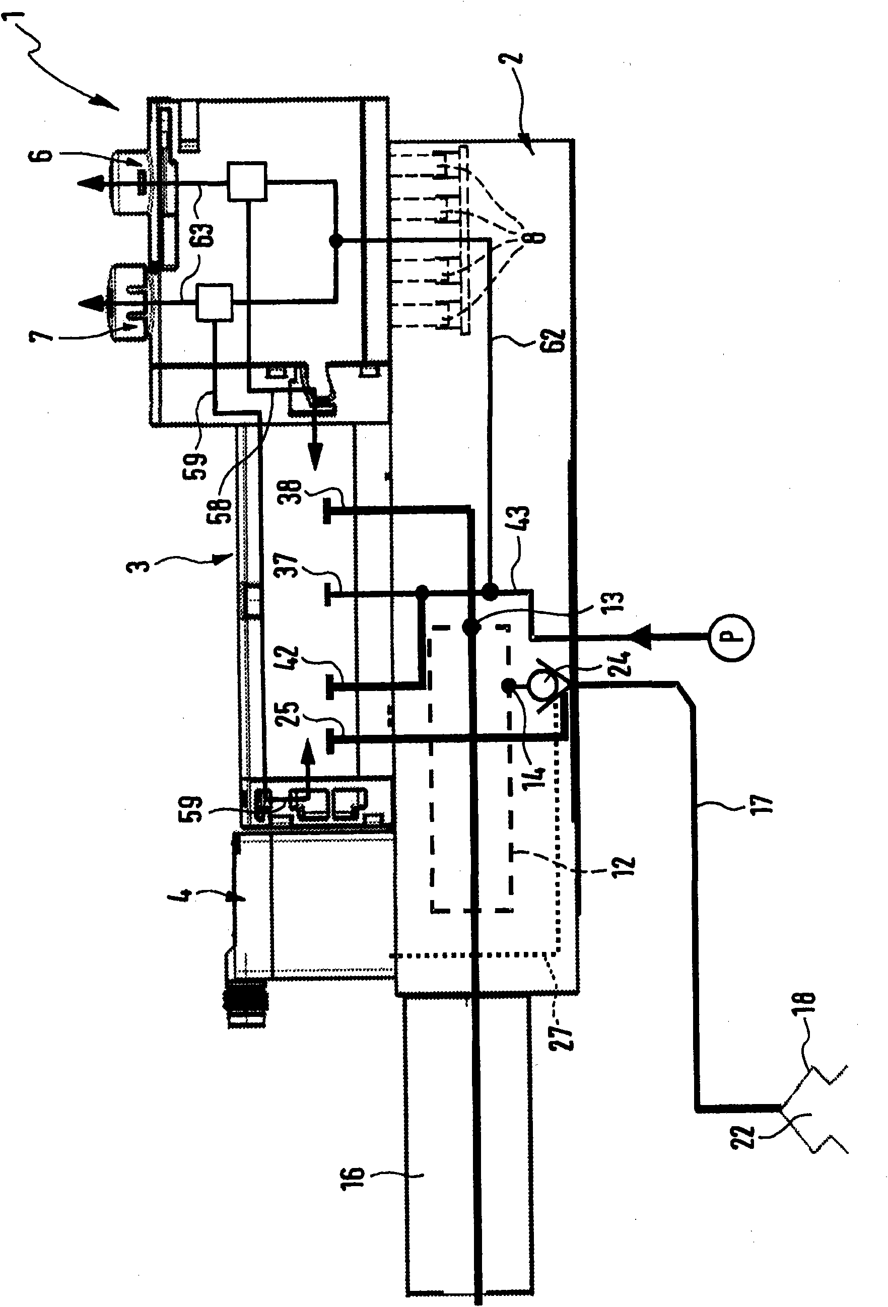
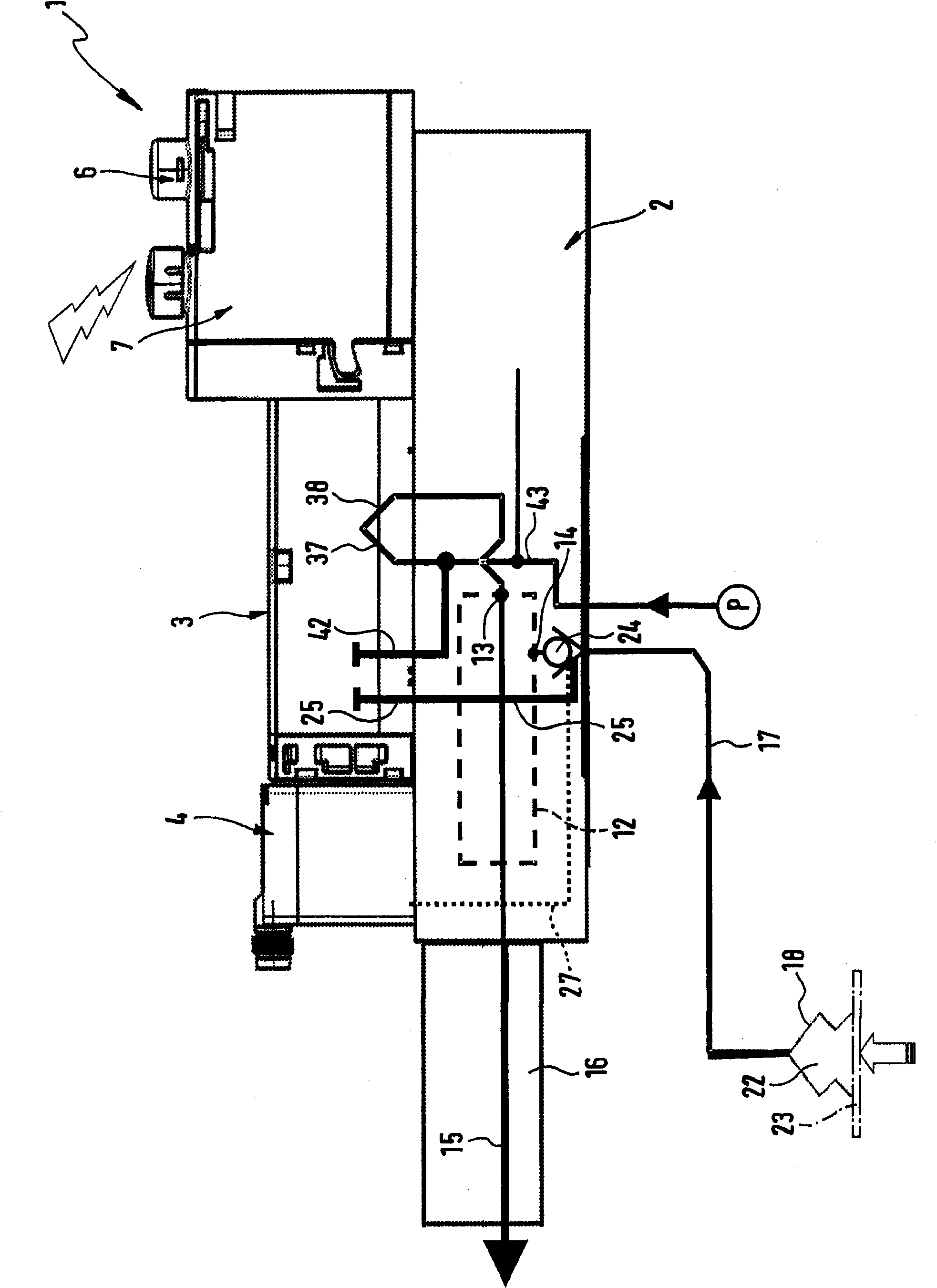
[0023] The vacuum generating device generally designated by the reference numeral 1 comprises, for example, a preferred functional block operating unit 2 to which a valve unit 3 and a pressure sensor device 4 are added.
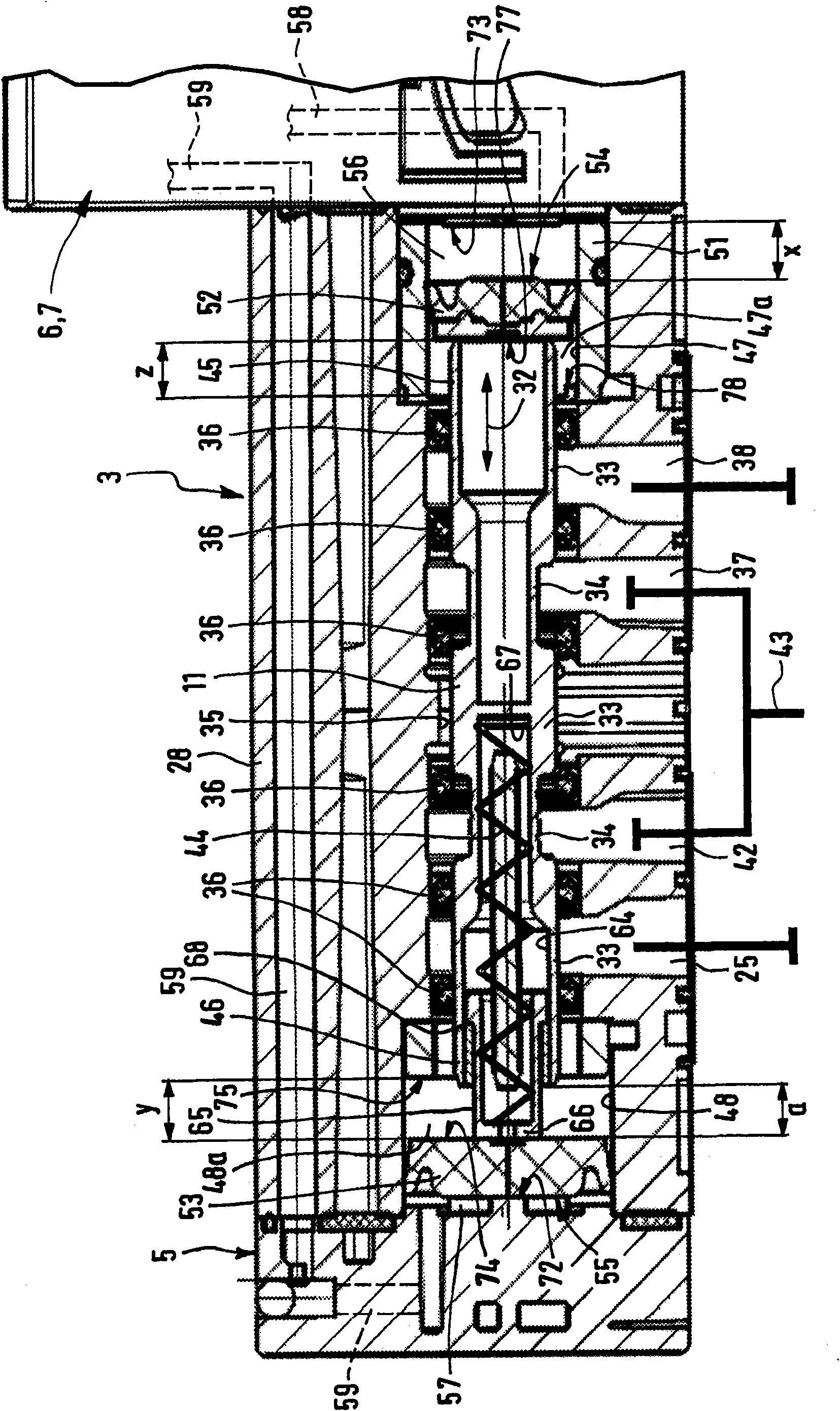
[0024] exist figure 2 , 4 , 5, 7 and 8, the valve unit 3, which is again partially illustrated separately, is designed as a control structure, in particular as a combined unit consisting of a main valve 5 and a first and a second electric- Pneumatic control valves 6 and 7 are composed. The control valves 6 and 7 can form on one side a control unit which is retrofitted to the main valve 5 .
[0025] The two control valves 6 and 7 are respectively 3 / 2-way valves. they pass through the figure 1 Only the electrical connections 8 shown schematically in the figure implement electrical operation, and they are individually controllable. The operating state of the control valves 6 , 7 predetermines the actual operating state of the main valve 5 and the operating...
PUM
 Abstract
Description
Claims
Application Information