Self-propelled turntable vehicle
A self-propelled, turntable technology, applied in the direction of transporting passenger cars, railway car body parts, laying tracks, etc., can solve the problems of occupying freight resources, long time consumption, low efficiency, and hindering the normal operation of the railway network, etc., to achieve simple structure, low noise, Noise fully practical effect
- Summary
- Abstract
- Description
- Claims
- Application Information
AI Technical Summary
Problems solved by technology
Method used
Image
Examples
Embodiment
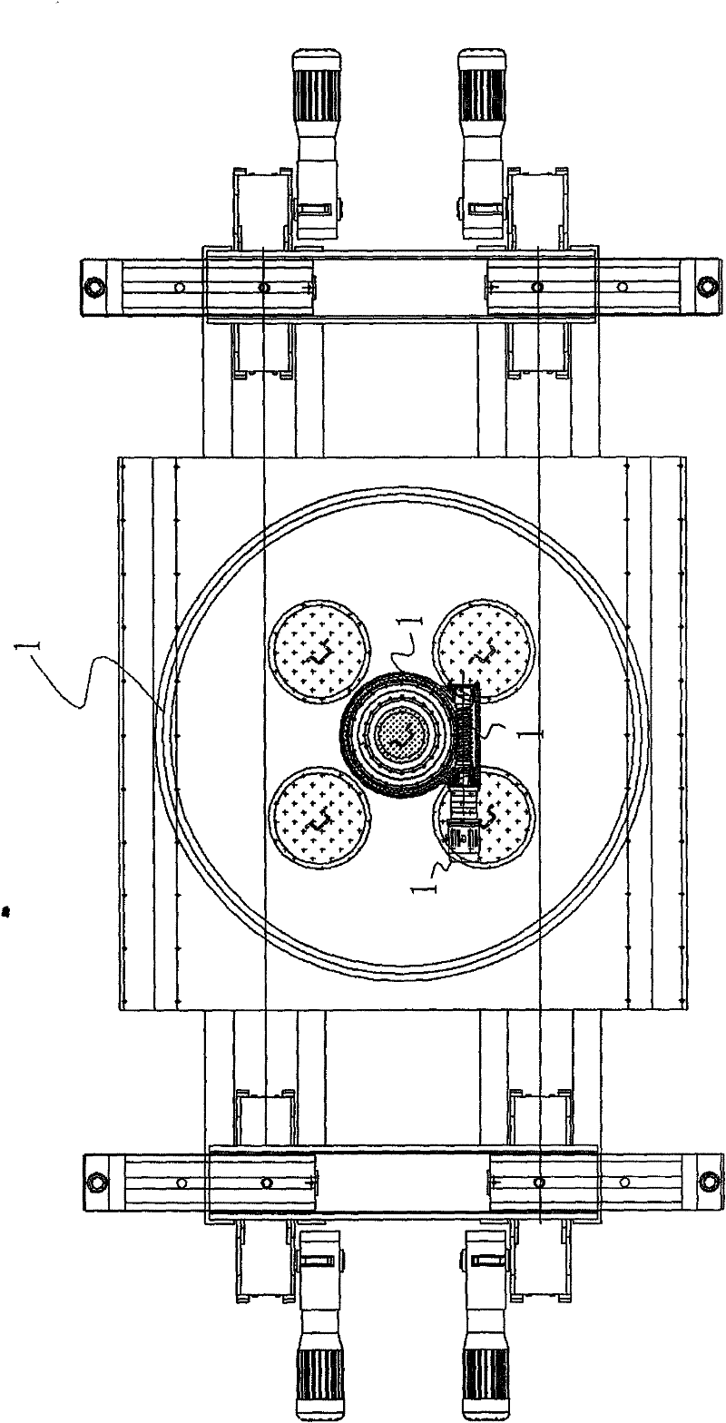
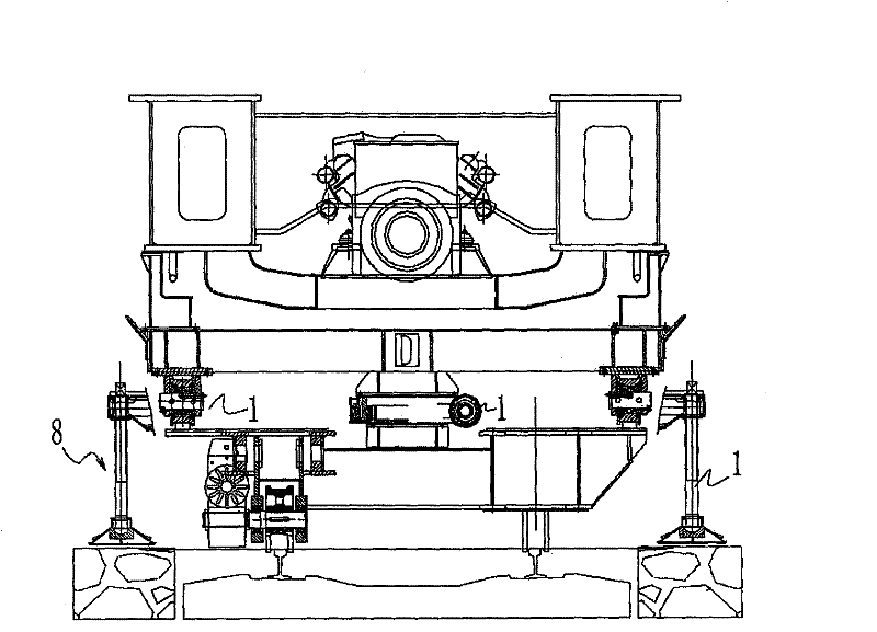
[0064] A self-propelled turntable car, characterized in that it includes a walking trolley 1 and a car body 2 arranged on the walking trolley 1, the car body 2 is provided with a rotary drive device 3 that can pass through the car body 2 Drive it to do the upper turntable body 4 of horizontal rotation. The traveling trolley 1 comprises a trolley frame 5 and four traveling wheel devices 6 arranged at the bottom of the trolley frame 5, the car body 2 is fixed with the trolley frame 5 by fixing bolts, and the trolley frame 5 is also provided with The frame 5 is vertically provided with at least two telescopic extension leg devices 7 . The traveling wheel device 6 includes a traveling wheel frame 8 and two traveling wheels 10 fixed on the traveling wheel frame 8 driven by a reduction motor 9 fixed on the traveling wheel frame 8 . The extended leg device 7 includes a single leg frame 11 and extended legs 12 fixed at both ends of the single leg frame 11 . At least two rotary row w...
Embodiment approach
[0069] Step 1. Vertical change rack:
[0070] Step 1.1. The distance between two hydraulic flip-mounting gantry frames is 25000mm. One is located at the front end of the car body, 9000mm from the front end, and the other is located at the rear end of the car body, 12000mm from the rear end. as follows Figure 4 shown.
[0071] Step 1.2. The foundation at the vertical replacement frame must be solid, the settlement of the foundation must not exceed the relevant standards, and at least two layers of sleepers should be placed.
[0072] Step 1.3. The two columns of the replacement frame are perpendicular to the horizontal plane, the verticality is ≤2 / 1000, the center of the replacement frame coincides with the center of the line, and the error is ≤10mm.
[0073] Step 2. The arm is separated from the car body, such as Figure 5 , Figure 6 and Figure 7 as shown,
[0074] Step 2.1. The bridge erecting machine is located at the track laying position, and the No. 0 column is r...
PUM
 Abstract
Description
Claims
Application Information
 - R&D
- Intellectual Property
- Life Sciences
- Materials
- Tech Scout
- Unparalleled Data Quality
- Higher Quality Content
- 60% Fewer Hallucinations
Browse by: Latest US Patents, China's latest patents, Technical Efficacy Thesaurus, Application Domain, Technology Topic, Popular Technical Reports.
© 2025 PatSnap. All rights reserved.Legal|Privacy policy|Modern Slavery Act Transparency Statement|Sitemap|About US| Contact US: help@patsnap.com


