
Foldable-type turnaround rack

A revolving rack and foldable technology, applied in the field of revolving racks, can solve the problems of easy twisting of left and right baffles and rear baffles, ineffective use of storage space, and insufficient positioning and connection, so as to achieve easy and convenient folding operation and structural design. Compact, good load-bearing effect

Active Publication Date: 2010-08-11
NINGBO MINTH AUTOMOTIVE PARTS RES&DEV CO LTD
View PDF6 Cites 13 Cited by
  • Summary
  • Abstract
  • Description
  • Claims
  • Application Information

AI Technical Summary

Problems solved by technology

[0003] Since the left and right baffles and the rear baffles of the turnover frame are always connected together, multiple columns need to be set on the base to make the folded turnover frame flat, and the left and right baffles are positioned relative to the base through the connection between the bolts and the columns, and then The baffle and the column are connected together by a simple hinge. The positioning connection of the left, right and rear baffles relative to the base is not stable enough, and the load-bearing capacity is not high. It is easy to twist between them, which is not conducive to the safe storage of objects, and accidents are prone to occur
In addition, the turnover rack is inconvenient to be stacked after being fully unfolded and fully folded, and the storage space cannot be effectively utilized.
[0004] In particular, the turnover frame can only be used for the turnover of glass. For some car accessories, such as narrow and long decorative strips, such a turnover frame still cannot be applied to this type of products

Method used


Image

  • Foldable-type turnaround rack
  • Foldable-type turnaround rack
  • Foldable-type turnaround rack

Examples


Embodiment Construction

[0029] The present invention will be further described in detail below in conjunction with the accompanying drawings and embodiments.

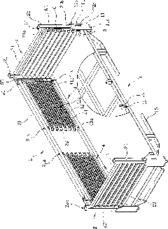
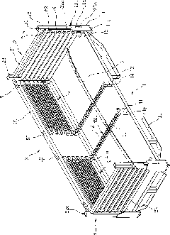
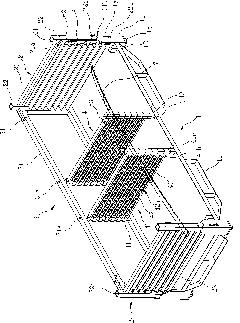
[0030] Such as Figure 1 to Figure 8 As shown, the foldable turnover frame includes a base 1, a middle frame 3 connected to the base 1, and two side frames 2 located on the left and right sides of the middle frame 3, and each side frame 2 and the middle frame 3 can be opposite to each other. The base 1 is independently folded and connected to the base 1;

[0031] Wherein, each of the four corners of the base 1 erects an L-shaped support plate 11 upwards, and the bottom edge of the base 1 is provided with a plurality of support feet 15;

[0032] Each side frame 2 comprises a cross bar 21 and two inside and outside vertical bars 22 that are connected with the end of the cross bar 21 respectively, and the bottom of each vertical bar 22 is positioned at the inner side of the L-shaped support plate 11, and each vertical bar 22 is connected by a pi...


PUM


Abstract

The invention relates to a foldable-type turnaround rack, which comprises a base (1), a middle bracket (3) and two side brackets (2), wherein an L-shaped supporting plate (11) is respectively and vertically arranged on four corners of the base (1), each side bracket (2) comprises a cross rod (21) and an inner and an outer vertical rods (22), and the outer side on the bottom part of each vertical rod (22) is connected with the inner side of the corresponding L-shaped supporting plate (11) in a pivot way; the middle bracket (3) comprises a basic framework (31), and the bottom edge of the basic framework (31) is connected with the surface of the base (1), and two ends of the upper edge of the basic framework (31) are respectively connected with one vertical rod (22) of each side bracket (2) respectively through a first plug pin (51). Compared with the prior art, the foldable-type turnaround rack is easy and convenient to fold, is firm and stable to connect, is difficult to twist, has good bearing capacity, can hold heavy objects, is easy to move, can be piled up to store when not in use, can be piled up when in use, and can maximally utilize the storage space.

Description

technical field [0001] The invention relates to a turnover frame used for storage and transportation of products or materials, in particular to a foldable folding turnover frame. Background technique [0002] At present, most of the turnover racks used for product and material storage adopt a stacked structure and are stacked in multiple layers to effectively utilize the storage space. The single-layer turnover frame is fixed, so stacking multiple layers takes a long time for workers to carry, and the stacking is labor-intensive, and the work efficiency of workers is not high. Thereby some foldable turnover frames are invented, and just disclose such a kind of turnover frame in the Chinese utility model patent " folding glass turnover frame " that is ZL97217498.2 (notification number is CN2299043Y) as the patent number. The turnover frame is specially designed for the storage and transportation of glass. It includes a base and a side rail. The side rail is composed of a rea...

Claims


Application Information

Patent Timeline
IPC IPC(8): B65D6/18B65D61/00B65D21/032
Inventor 黄荣林
Owner NINGBO MINTH AUTOMOTIVE PARTS RES&DEV CO LTD
Learn More