An illumination control device in an endoscopic imaging system

An imaging system and lighting control technology, applied to the coupling of endoscopes, measuring devices, and optical waveguides, can solve the problems of rings or uneven distribution of illumination intensity, limited illumination intensity control level, etc.

Active Publication Date: 2010-08-11
JOHNSON & JOHNSON GMBH
View PDF0 Cites 8 Cited by
  • Summary
  • Abstract
  • Description
  • Claims
  • Application Information

AI Technical Summary

Problems solved by technology

First, these fixtures can cause ringing or uneven distribution of illumination intensity
Additionally, most of these controls provide a limited level of control over lighting intensity

Method used


Image

  • An illumination control device in an endoscopic imaging system
  • An illumination control device in an endoscopic imaging system
  • An illumination control device in an endoscopic imaging system

Examples


Embodiment Construction

[0017] Although the invention will be described in connection with a few embodiments as shown in the drawings, those skilled in the art will readily recognize that many additional embodiments would be well within the scope of the invention, the scope of which is defined by the claims presented. Accordingly, the following detailed description is intended to illustrate the present invention only and is not intended to limit the scope and spirit of the claimed invention in any way. In this regard, certain definitions of the terms used in the claims are adapted to ensure that the reader will not be construed as limiting these terms to the specific preferred embodiments described in this detailed description. These definitions are given by way of example only and not limitation.

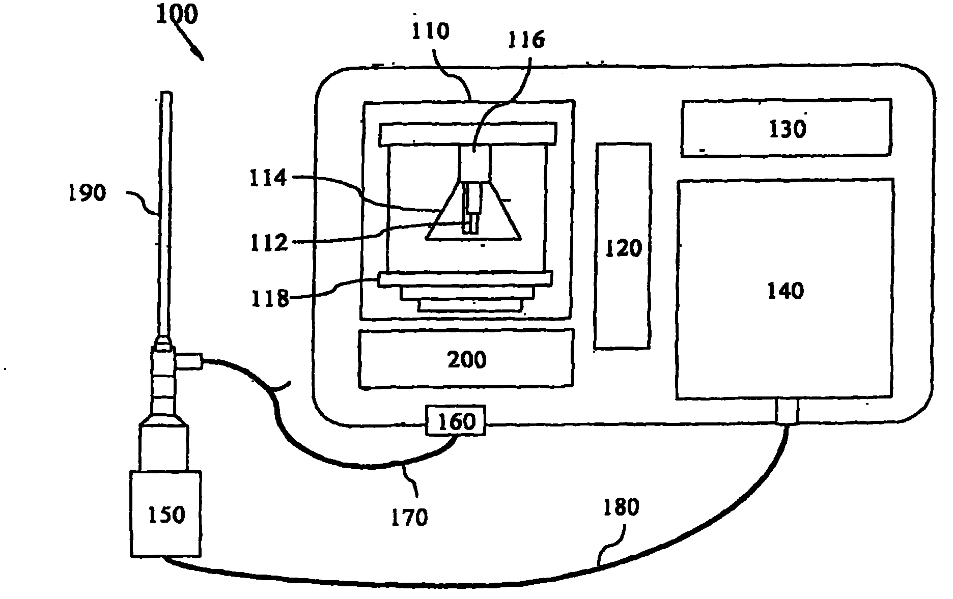
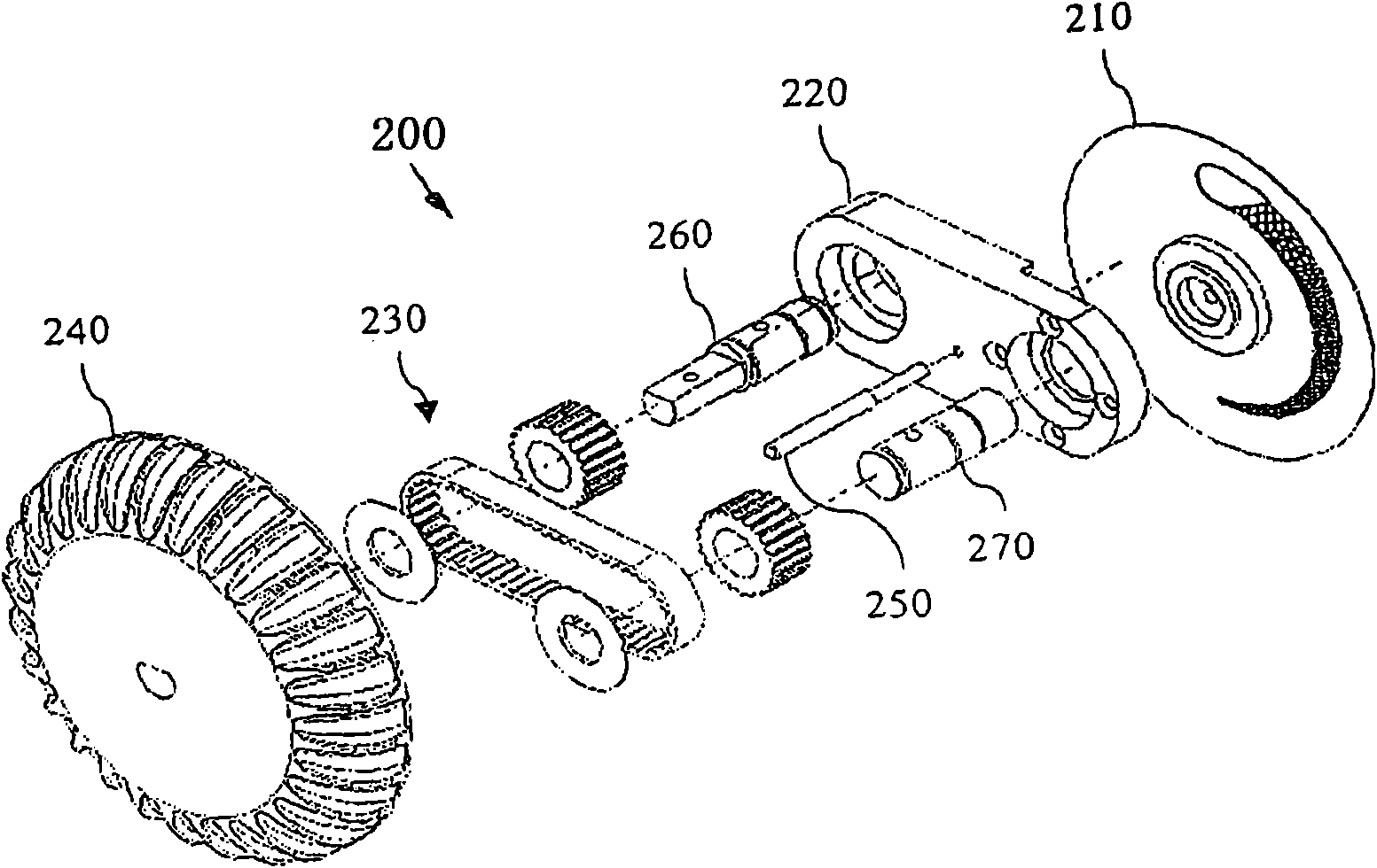
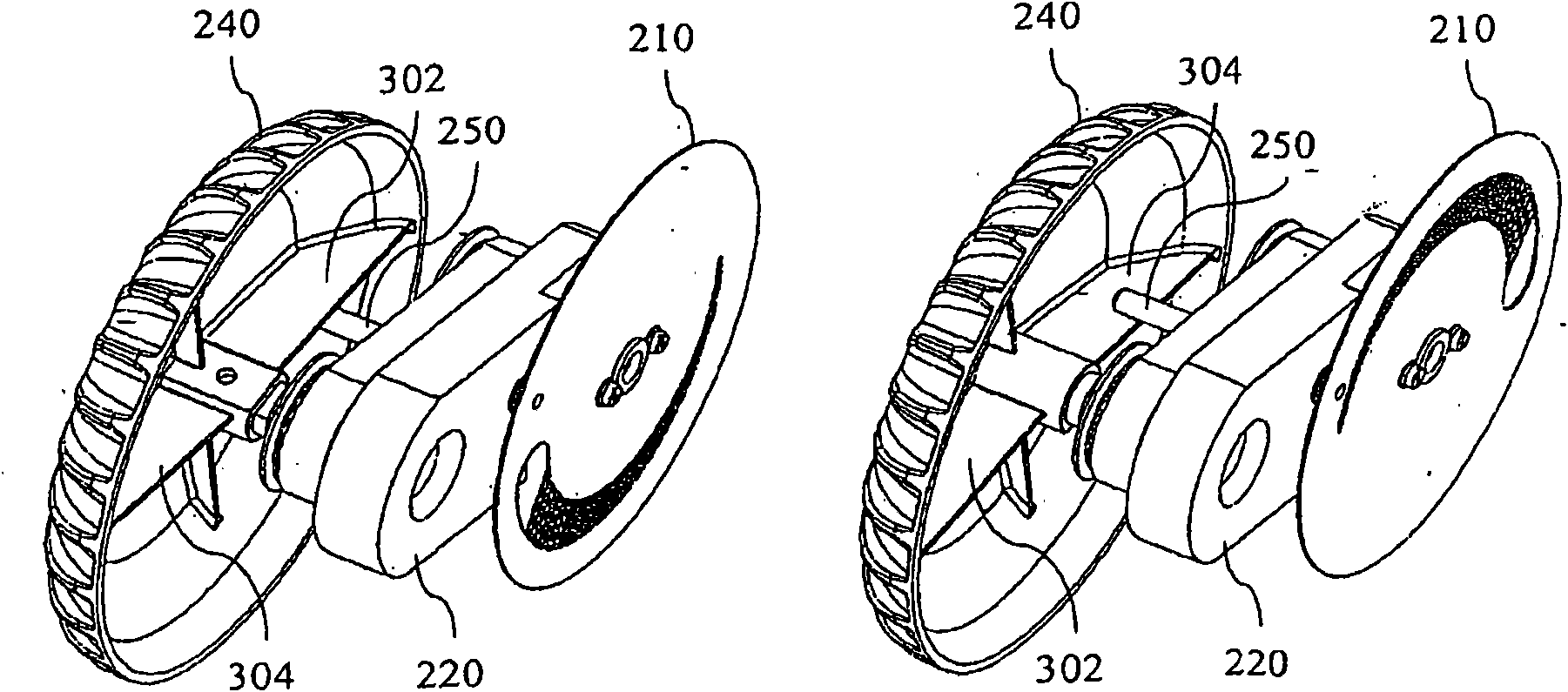
[0018] The terms "optical fiber" and "optical cable" as used herein are intended to typically denote a flexible optical conductor comprising a plurality of optical fibers, such as glass fibers, in the for...


PUM


Abstract

This invention relates to an illumination control device (200) in an endoscopic imaging System comprising; a control member (210) wherein the control member comprises; an aperture (404) in the form of a variable opening in a carrying or bearing member (402), and disposed between the optical port (160) and the light source (112), the movement of the aperture (404) across the optic port (160) corresponding to the movement of the control member (210) controls the area of the optic port (160) transmitting the light to the endoscope (190), and in turn controlling the illumination intensity at the examination site; and a grating (406) having at least two holes (410, 412), the pattern of the holes (410, 412) being variable across a guiding curve (414) so as to gradually vary the opacity of the grating (406), the illumination intensity control being dependent on the width of the aperture (404) and the opacity of the grating (406).

Description

technical field [0001] The present invention generally relates to an illumination control system, in particular to an illumination control device for an endoscope light source. Background technique [0002] Minimally invasive procedures or surgery (MIP or MIS), including endoscopic, laparoscopic, endoscopic-assisted or laparoscopic-assisted procedures, are known and offer benefits to the patient, such as limited incisional trauma, reduced pain, limited scarring, fewer hospitalizations and an earlier return to normal functional status. To perform such procedures, an external light source, typically coupled to an optical fiber and an endoscope, is used to illuminate the surgical space. Typically, it is desirable to control the intensity of the illumination to improve and adjust the display of the site according to the needs of the surgeon, operator and / or medical practitioner. [0003] Several techniques and devices are used to control the intensity of the illumination, such...

Claims


Application Information

Patent Timeline
Patent Type & Authority Applications(China)
IPC IPC(8): A61B1/07
CPCG02B6/34G01J1/04G01J1/0407A61B1/07G02B6/3594A61B1/0646A61B1/0669A61B1/0655
Inventor D·普佐丹G·M·恰范H·贾殷S·V·帕拉克
Owner JOHNSON & JOHNSON GMBH
Why Eureka
Try Eureka