Pneumatic tire

A technology for pneumatic tires and treads, which is applied in the direction of pneumatic tires, tire parts, tire treads/tread patterns, etc., and can solve problems such as inability to configure transverse grooves, difficulty in obtaining tire overall balance, and obvious high-frequency noise. To achieve the effect of improving uneven wear resistance, improving drainage, and reducing high-frequency noise

Inactive Publication Date: 2010-08-11
BRIDGESTONE CORP
View PDF1 Cites 12 Cited by
  • Summary
  • Abstract
  • Description
  • Claims
  • Application Information

AI Technical Summary

Problems solved by technology

However, when the circumferential main groove is added, there is a problem that high-frequency noise due to resonance inside the circumferential main groove becomes conspicuous
[0005] In conventional pneumatic tires with non-directional asymmetric treads, in order to suppress the flow to the vehicle side during handling on dry and wet roads, it is not possible to arrange lugs with a small inclination angle with respect to the tire circumferential direction. groove
[0006] In lug grooves formed with a large inclination angle with r

Method used


Image

  • Pneumatic tire
  • Pneumatic tire
  • Pneumatic tire

Examples


Embodiment approach

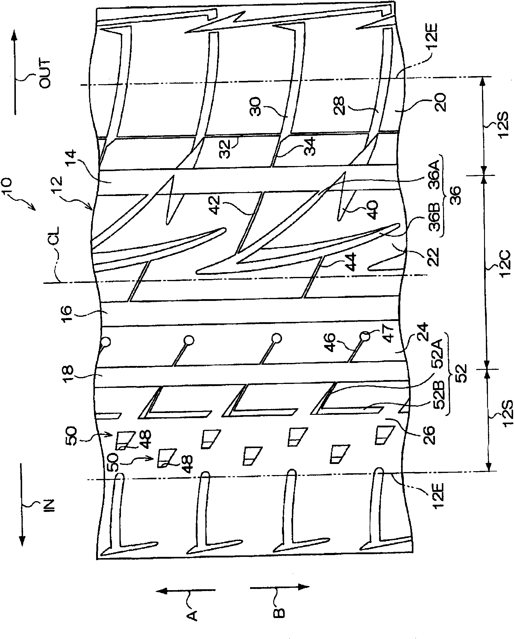
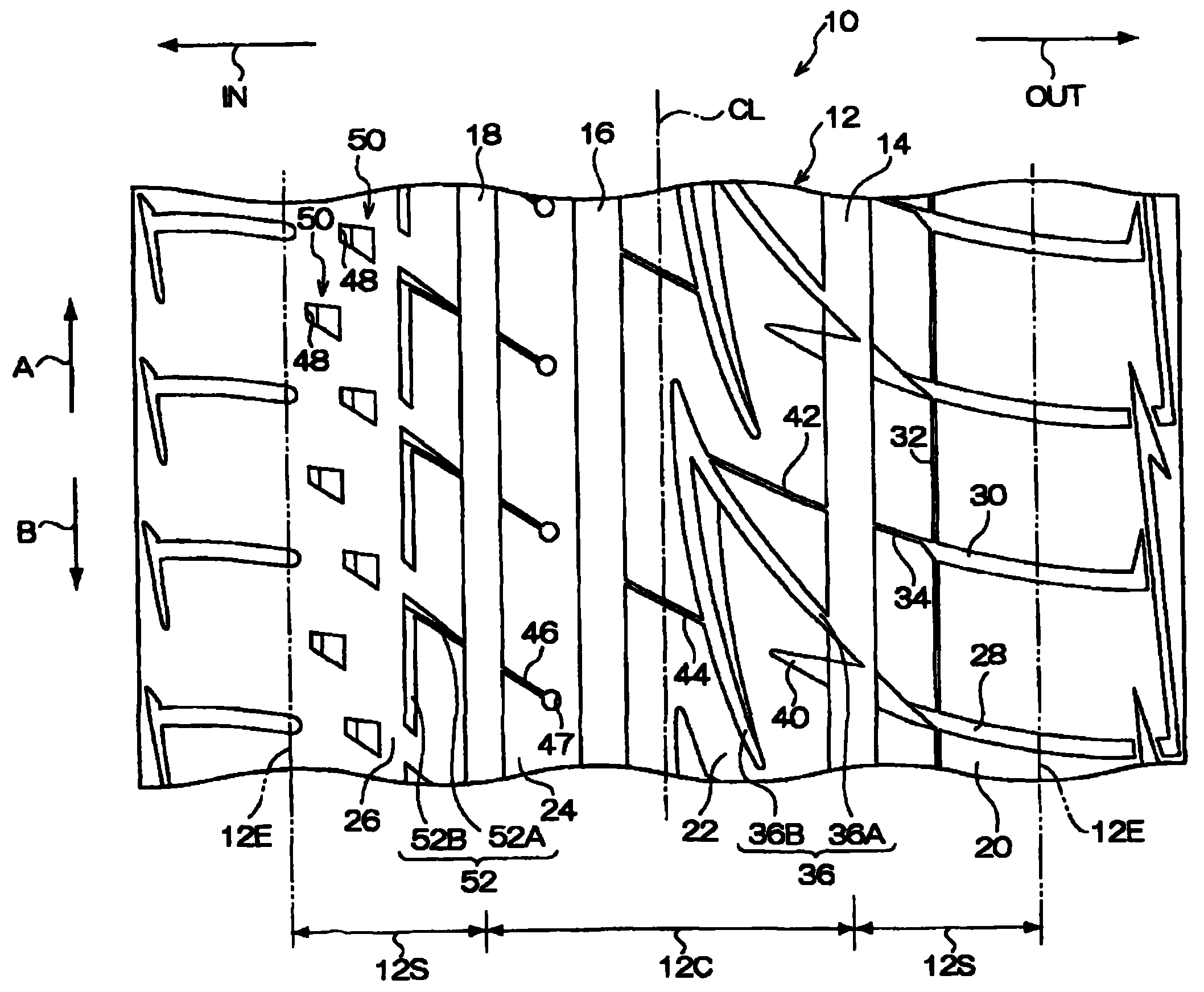
[0078] The fourth land portion 26 on the innermost side when mounted on a vehicle is a land portion that requires severe uneven wear. 90°, the rigidity of the fourth land portion 26 can be ensured, and the uneven wear resistance of the fourth land portion 26 can be improved.

Embodiment

[0081] Example: It is a pneumatic tire having the tread pattern of the above-mentioned embodiment. In addition, its groove depth is 8.3 mm. The groove width of the first circumferential main groove was 8.5 mm, the groove width of the second circumferential main groove was 9.0 mm, and the groove width of the third circumferential main groove was 7.5 mm. The width of the first land portion was 30 mm, the width of the second land portion was 35 mm, the width of the third land portion was 13.2 mm, and the width of the fourth land portion was 32 mm. On the other hand, the inclination angle of the V-shaped groove is 45° on the main groove side in the first circumferential direction, and is 30° near the curved portion. Furthermore, the circumferential pitch length of the V-shaped grooves is 58 mm, and the circumferential pitch length of the L-shaped grooves is 28 mm.

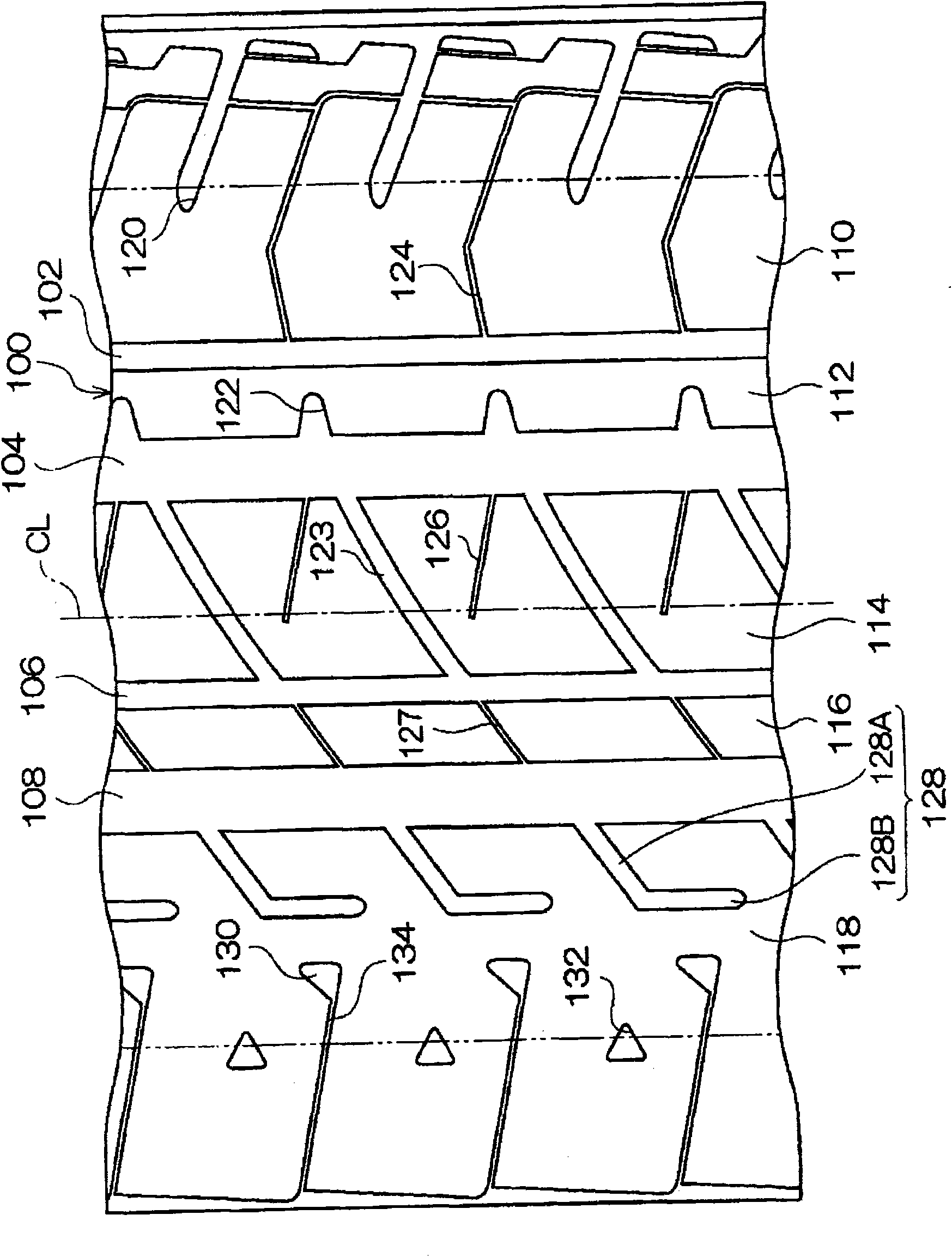
[0082] Previous example: Yes figure 2 Pneumatic tires with the tread pattern shown. In addition, in figure 2 ...


PUM

PropertyMeasurementUnit
Groove depthaaaaaaaaaa

Abstract

A pneumatic tire simultaneously achieves improved water discharge characteristics and reduced noise. Fundamental water discharge performance is secured by providing a tread (12) with a first circumferential main groove (14), a second circumferential main groove (16), and a third circumferential main groove (18). V-shaped grooves (36) connected to the first circumferential main groove (14) are formed in a second land section (22) in a tread center region, and this secures water discharge characteristics and eliminates high frequency noise. On the other hand, L-shaped grooves (52) connected to the third circumferential main groove (18) are formed in a fourth land section (26) located on the side facing the vehicle, and this secures water discharge characteristics and eliminates high frequency noise. Excellent water discharge and low noise characteristics are simultaneously achieved by positioning the V-shaped grooves (36) on the side opposite the vehicle when the tire is mounted on it and positioning the L-shaped grooves (52) on the vehicle side.

Description

technical field [0001] The present invention relates to a pneumatic tire, and more particularly, to a pneumatic tire having improved resistance to uneven wear of a land contact portion on the innermost side in the vehicle width direction when mounted on a vehicle. Background technique [0002] In summer tires where performance balance is important, a block pattern combining linear main grooves extending in the tire circumferential direction and lug grooves inclined relative to the tire circumferential direction is generally used (see Patent Document 1). Furthermore, in order to obtain high performance, the tread pattern is made left and right asymmetrical. In addition, there is a problem that rotation is restricted in a directional pattern, which makes it difficult to use, so a non-directional pattern is often used. [0003] Also, in the case of a non-directional asymmetric pattern, the lug grooves have a large angle with respect to the tire circumferential direction. [0...

Claims


Application Information

Patent Timeline
IPC IPC(8): B60C11/04B60C5/00
CPCB60C11/0304B60C2011/0381B60C11/12
Inventor 越智直也
Owner BRIDGESTONE CORP
Why Eureka
Try Eureka