Motor terminal portion structure

A terminal part and motor technology, applied in the direction of the casing/cover/support, electrical components, electromechanical devices, etc., can solve the problems of water immersion into the insulating parts, and the generalization of the parts is not ideal, so as to improve the assembly operability, Reliable blocking and reduction of the number of parts

Active Publication Date: 2006-11-15
HONDA MOTOR CO LTD
View PDF0 Cites 6 Cited by
  • Summary
  • Abstract
  • Description
  • Claims
  • Application Information

AI Technical Summary

Problems solved by technology

[0004] However, in order to discharge the water in the insulating member from the above-mentioned drain hole, it is necessary to expose at least a part of the drain hole from the insulating cover mounted on the insulating member. It may cause water to easily infiltrate into the insulating part through the drain hole.
[0005] In addition, at this time, it is conceivable to change the position of the drain hole of the insulating member according to the layout of the motor, but in this case, it is necessary to set various insulating members, so it is not ideal in terms of common use of parts.

Method used


Image

  • Motor terminal portion structure
  • Motor terminal portion structure
  • Motor terminal portion structure

Examples


Embodiment Construction

[0033] Embodiments of this invention will be described below with reference to the drawings.

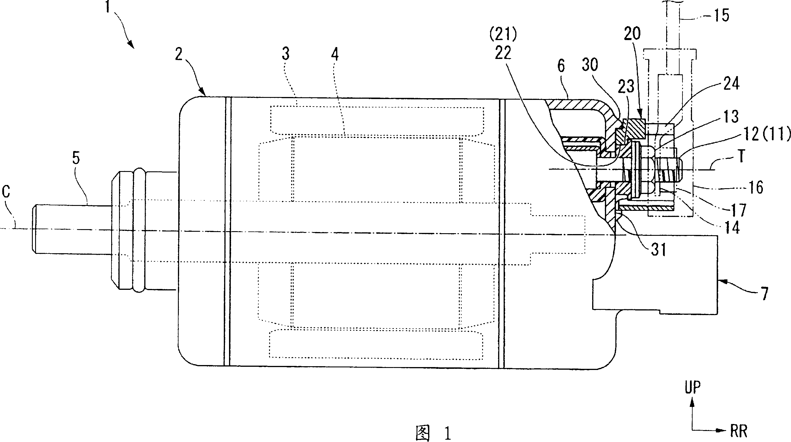
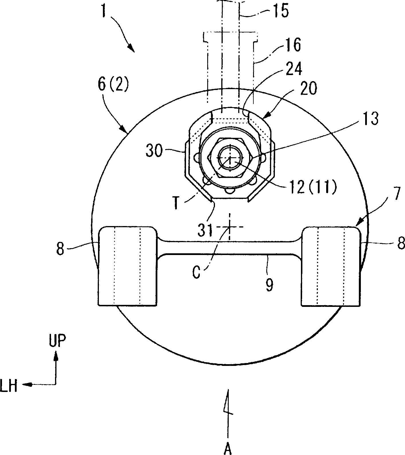
[0034] The motor 1 shown in Figures 1 and 2 is, for example, a starter motor of an automatic two-wheeled vehicle, and has a substantially cylindrical casing 2, a stator 3 is fixed on the outer peripheral side of the casing 2, and a stator 3 is fixed on the inner peripheral side thereof. The rotor 4 is rotatably arranged. The rotor 4 is integrated with a rotating shaft 5 penetrating therethrough, and the rotating shaft 5 is rotatably supported by the casing 2 .

[0035] Then, the rotor 4 and the rotating shaft 5 are integrally driven to rotate by the electric power supplied from the vehicle-mounted battery to the motor 1 . Such a motor 1 is mounted on a vehicle with its rotation axes C substantially parallel. In the following description, the arrow RR in the figure indicates the rear along the direction (axial direction) of the above-mentioned rotation axis C of the motor 1 assemble...


PUM


Abstract

A motor terminal portion structure is provided which can satisfactorily drain the water in an insulating member surrounding the outer circumference of a terminal and prevent water from entering the insulating member, in addition to allowing the insulating member to be commoditized without being influenced by motor layout. A motor terminal portion structure includes an insulator that is formed in a cylindrical shape surrounding the outer circumference of a terminal and is secured to a bracket. A drain hole is provided to establish communication between the inside and outside of the insulator. A flange portion shields an opening of the drain hole on the outside of the insulator. A plurality of the drain holes are disposed around the terminal. The outer side surface of the insulator and the inside surface of the flange portion are each formed in regular polygon so as to conform to each other. A portion of the flange portion facing vertically downward in an on-board state is formed as a notch.

Description

technical field [0001] The present invention relates to a terminal portion structure of a motor mounted on a vehicle. Background technique [0002] Conventionally, among the above-mentioned structures, there is a structure in which drains are provided at four places around the periphery of a dish-shaped insulator (insulation member) attached to a terminal (terminal) of an alternator (motor). A structure using slits (drainage holes) (for example, see Patent Document 1). [0003] Patent Document 1: Patent No. 3027900 [0004] However, in order to discharge the water in the insulating member from the above-mentioned drain hole, it is necessary to expose at least a part of the drain hole from the insulating cover mounted on the insulating member. When it is on, it may cause water to easily infiltrate into the insulating part from the drainage hole. [0005] In this case, it is conceivable to change the position of the drain hole of the insulating member according to the motor...

Claims


Application Information

Patent Timeline
Patent Type & Authority Applications(China)
IPC IPC(8): H02K5/22
CPCH02K5/225
Inventor 柳泽毅新川国明北嶋毅
Owner HONDA MOTOR CO LTD
Why Eureka
Try Eureka