Measuring device and measuring instrument and/or machine tool

A technology for measuring devices and tools and equipment, which is applied in the direction of measuring devices, identification devices, measured value indications, etc., and can solve problems such as the thickness of the indicating unit and the limitation of the shape selection of the indicating unit

Inactive Publication Date: 2010-08-11
ROBERT BOSCH GMBH
View PDF0 Cites 1 Cited by
  • Summary
  • Abstract
  • Description
  • Claims
  • Application Information

AI Technical Summary

Problems solved by technology

Since such indicating units are essentially limited to one-dimensional flat structures, this limits the possibilities of shape options for such indicating units.
This is particularly problematic in the case of display units in measuring devices and/or tool devices that partly have an

Method used


Image

  • Measuring device and measuring instrument and/or machine tool
  • Measuring device and measuring instrument and/or machine tool
  • Measuring device and measuring instrument and/or machine tool

Examples


Embodiment Construction

[0014] The same components and components with the same function are shown in the figures with the same reference numerals.

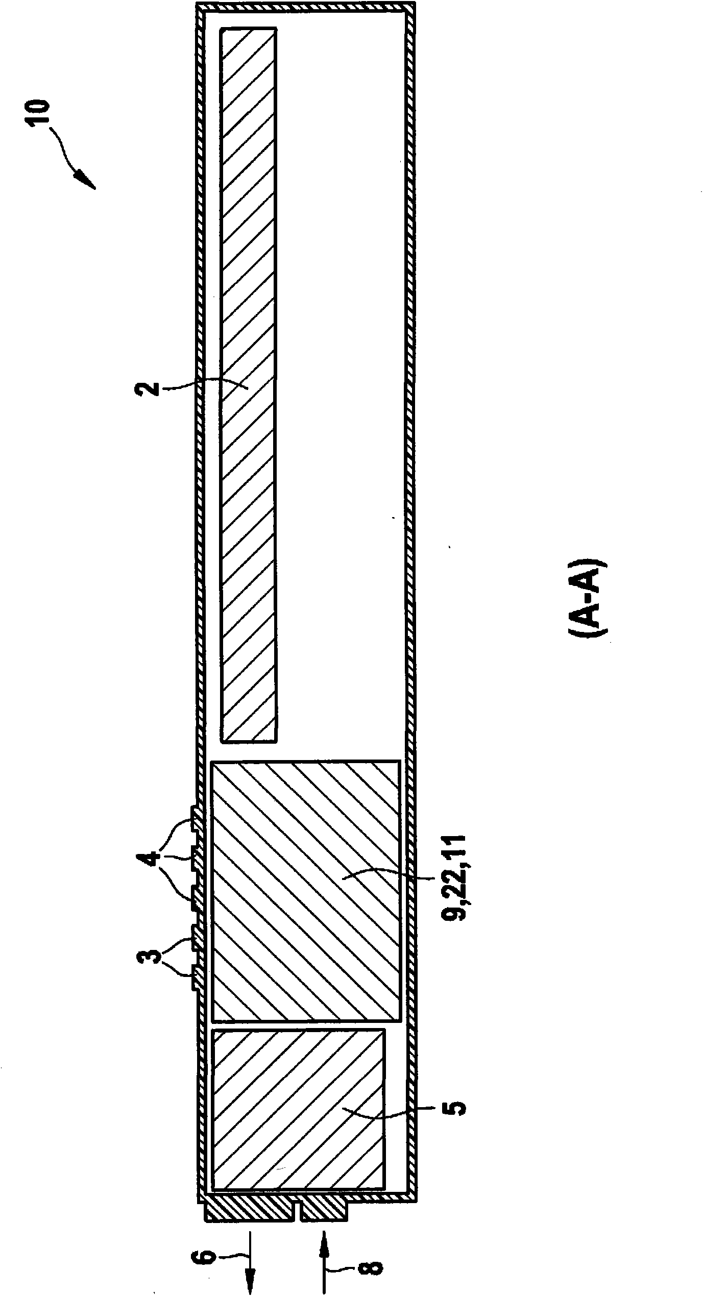
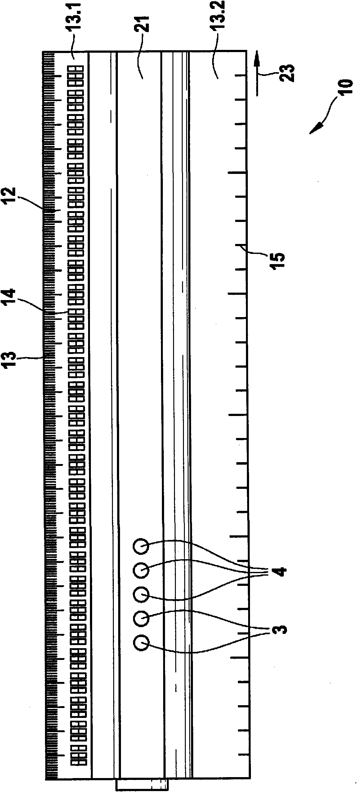
[0015] Two embodiments according to the invention are described below within the scope of a portable device for contact distance measurement according to FIG. 1 or for contactless distance measurement according to FIG. emission and reflection. In contrast to the direct, i.e. tactile, distance measurement, for example by direct comparison of the distance between two points with the aid of a ruler 10 or a graduated scale 15 shown in FIG. The runtimes of the transmitted and reflected measurement signals 6, 8 are compared with each other and transmitted via the electronics unit 11 to a display unit with a display unit 12 configured as a long scale and provided for reading the measured values .

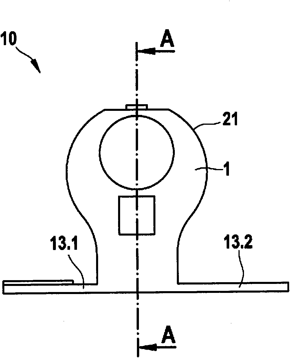
[0016] To this end, FIG. 1 shows a distance measuring device 10 , which is shown in FIG. A as a longitudinally extending cross-section, in FIG. B as an end view, ...


PUM


Abstract

The invention relates to a measuring device comprising a representation unit in which an electro-optical representation unit (12) is combined with an electronic unit (11) in a circuit arrangement, the representation unit (12) being adapted to represent a result of measurement so that it can be read and the electronic unit (11) being adapted to control the representation of the result of measurement. In order to improve the comparatively thick and inflexible measuring devices of the prior art, the representation unit (12) is applied to a thin support to give a flexible layer arrangement.

Description

technical field [0001] The invention relates to a measuring device with a display unit, in which an optoelectronic display unit is arranged in a circuit arrangement, in particular in combination with an electronic unit, wherein the display unit is designed to display a measurement result in a readable manner, and the electronic unit is designed to use to control the display of the measurement results. Background technique [0002] Measuring devices of this type are known, for example, with liquid crystal displays. Such liquid crystal indicators are used, for example, in hand-held machine tools, where display units based on liquid crystal indicators are usually equipped with a glass or plastic housing in the transparent area in order to protect the unit from damage caused by impacts and blows. Since such indicating units are essentially limited to one-dimensional flat structures, this limits the possibilities of shape options for such indicating units. This is particularly ...

Claims


Application Information

Patent Timeline
IPC IPC(8): G01D7/00G01B3/02G09F9/30
CPCG01B3/04G01D7/00
Inventor S·蒂德
Owner ROBERT BOSCH GMBH
Why Eureka
Try Eureka