Multi-joint mechanical arm mechanism

A multi-joint robotic arm and joint technology, applied in the direction of manipulators, claw arms, joints, etc., to achieve the effect of convenient folding and reduced storage space

Inactive Publication Date: 2010-08-18
HARBIN ENG UNIV
View PDF8 Cites 17 Cited by
  • Summary
  • Abstract
  • Description
  • Claims
  • Application Information

AI Technical Summary

Problems solved by technology

The application number is 200810040451.2, and the title is "Large-angle Rotary Joint Mechanism of Robotic Arm" and other public documents, although there are public reports about the robotic arm, but they cannot meet the above requirements

Method used


Image

  • Multi-joint mechanical arm mechanism
  • Multi-joint mechanical arm mechanism
  • Multi-joint mechanical arm mechanism

Examples


Embodiment Construction

[0015] The present invention is described in more detail below in conjunction with accompanying drawing example:

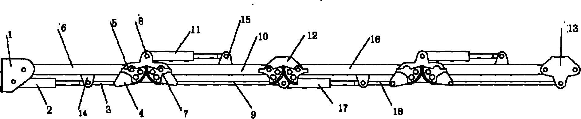
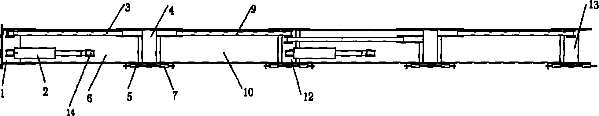
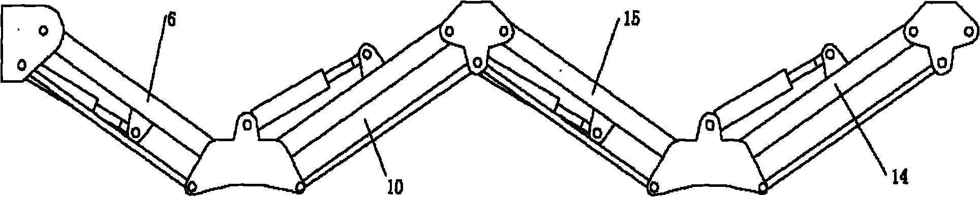
[0016] combine figure 1 with 2 , the present embodiment is a 4-section mechanical arm mechanism. Among them, joint 1 is the starting joint, which is mainly used for the starting end of the multi-joint mechanical arm. On the one hand, it facilitates the fixed connection of the arm with other mechanisms; The movable joint 4 links to each other. The first movable joint 4 is another joint that simultaneously combines Figure 4 , this joint is mainly used for the connection of arm 6 and arm 10. The first movable joint 4 is in the shape of an airplane, and the connecting rod 3 and the connecting rod 9 are connected with the joint 4 through the shaft holes 4a-1, 4a-2 by using pivot pins; the arm 6 and the arm 10 are connected by pivot pins through the shaft holes 4b-1, 4b-2 is connected to joint 4. If the arm 6 and the arm 10 need to be synchronized, then on the fi...


PUM


Abstract

The invention provides a multi-joint mechanical arm mechanism. Two sub-arms are connected through a specific joint, and every two adjacent joints have incompletely same structures. Besides arms, a connecting rod is connected among every two joints, and the connecting rod, the sub-arms and the joints thereof form a parallelogram. In addition, the joints and the arms are connected through a cylinder. Some section of the cylinder is driven to extend out to a proper position, thus the section of the sub-arm can unbend, otherwise, the section of the sub-arm is driven to fold. As required, the invention can arbitrarily deform the mechanical arm so as to satisfy the requirements of different operation tasks. The mechanism can realize the over-length requirement of the arm, is convenient to fold and greatly reduces the transportation and storage space. In addition, the mechanism can get rid of length restriction based on multiple sections of telescopic cylinders, and the joints and folding arms can be increased and decreased according to requirements, thereby being convenient for the flexibly design of long arms and super long arms.

Description

technical field [0001] The patent of the present invention relates to a multi-joint mechanical arm. Background technique [0002] In engineering practice, the design of long mechanical arms and ultra-long mechanical arms has always been a difficult point in engineering design. This type of mechanical arm not only needs to be able to meet the operation requirements in terms of length, but also needs to consider the installation, transportation and other aspects of the mechanical arm. Storage site requirements. At present, the design of mechanical long arms mostly adopts multi-section telescopic mechanical arms, and the expansion and contraction of the mechanical arms is realized through multi-section telescopic oil cylinders, such as aerial work cranes. In addition, in many special working environments, limited by space and location, in order to complete specific tasks, the robotic arm also needs to have the ability to fold and deform arbitrarily, and can be deformed accordi...

Claims


Application Information

Patent Timeline
Patent Type & Authority Applications(China)
IPC IPC(8): B25J18/00B25J17/00
Inventor 梁利华史洪宇吉明张松涛王经甫宋吉广杨生
Owner HARBIN ENG UNIV
Why Eureka
Try Eureka