Plastics suction mould

A technology of plastic-absorbing mould, plastic-absorbing part frame, applied in the field of plastic-absorbing mould, to achieve the effect of saving raw materials, reducing stretching, and improving production success rate

Active Publication Date: 2012-05-23
SHANGHAI TONGLING AUTOMOTIVE TECH INC
View PDF0 Cites 0 Cited by
  • Summary
  • Abstract
  • Description
  • Claims
  • Application Information

AI Technical Summary

Problems solved by technology

If the mold is forced out, the sharp corners of the film are easy to break
When mounting, the rupture of the film will also cause the film to fail to cover the plastic surface, and the plastic will be injected into the film surface
Seriously affect the production quality of the film. At present, when producing the blister film for the press frame before the improvement, the reject rate reaches about 80%, the production success rate is low, and the production cost is greatly increased.

Method used


Image

  • Plastics suction mould
  • Plastics suction mould
  • Plastics suction mould

Examples


Embodiment 1

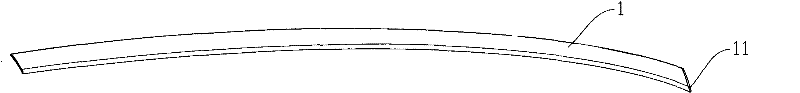
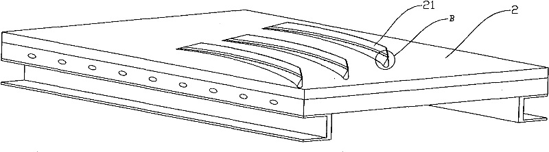
[0035] The press frame 3 includes a press frame base 4 and a plastic-absorbing part frame 5, and the shape of the plastic-absorbing part frame 5 is the same as that of the plastic-absorbing part to be manufactured. The plastic-absorbing part frame 5 is arranged on the upper end of the pressure frame base 4 . The molded frame 5 of the plastic-absorbing part extends outward along the base body 4 of the press frame, that is, the mold frame 5 of the plastic-absorbing part is larger than the base body 4 of the press frame.

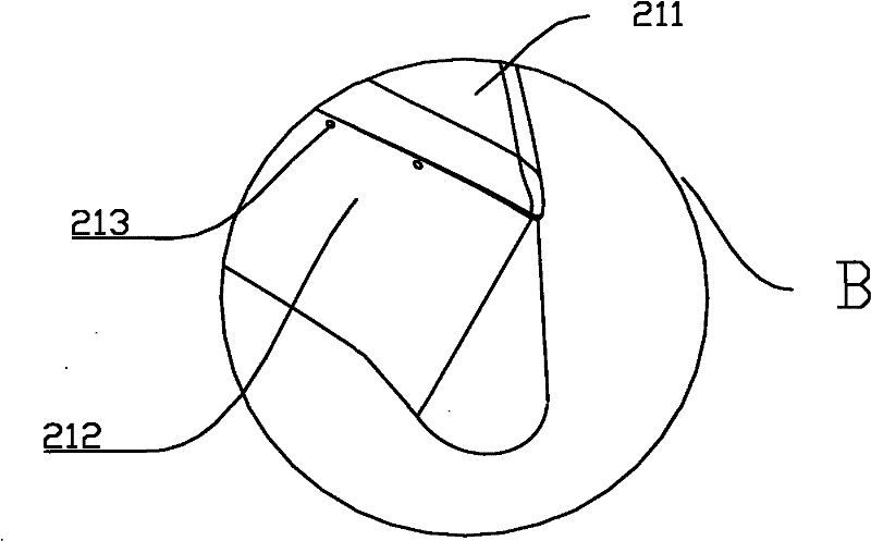
[0036] There is a first sharp corner 51 on the plastic part frame 5, and the first sharp corner 51 is an arc angle between the two sides (52, 53) of the bottom surface of the plastic part frame 5, and its two sides (52, 53) pass through The arc segments 54 are connected, and the central angle corresponding to the arc segments 54 is the first sharp angle. The bottom surface refers to the surface that cuts the plastic forming frame 5 along a direction parallel t...

Embodiment 2

[0046] The embodiments in the present invention are only used to illustrate the present invention, and do not constitute a limitation to the scope of the claims. Other substantially equivalent substitutions that can be thought of by those skilled in the art are within the protection scope of the present invention.


PUM


Abstract

The invention discloses a plastics suction mould, comprising press frames, wherein the press frames comprise press frame substrates and plastics suction part fixture; and the plastics suction part fixture is arranged at the upper end of the press frame substrates and is provided with first acute angles. The invention is characterized in that convex plates which extend outwards along the press frame substrates are arranged on the press frame substrates, positioned below the first acute angles and distant from the plastics suction part fixture. The plastics suction mould can reduce the under-cut depth and drawing of the thin films, thereby improving the mould yield.

Description

technical field [0001] The invention relates to a blister mold. Background technique [0002] Automotive interior parts are generally in the form of decorative films mounted on the surface of injection molded parts. Before the film is mounted on the surface of the injection molded part, it needs to be formed by blister, and then punched after forming. It is best to attach the die-cut film to the surface of the injection molded part. The shape of the interior trim varies depending on where it is installed. One of the trim pieces is a shape with an included angle. Therefore, the film that requires its surface mount must also have an included angle. like figure 1 Shown is a schematic view of the final shape of a film, the film 1 being provided with sharp corners 11 . [0003] Blister molding molds, such as figure 2 , image 3 As shown, the mold frame 2 is included, and the mold frame 2 is provided with a pressure frame 21. The mold frame 2 has an air cavity (not shown...

Claims


Application Information

Patent Timeline
Patent Type & Authority Patents(China)
IPC IPC(8): B29C51/36
Inventor 江德生康飞斌
Owner SHANGHAI TONGLING AUTOMOTIVE TECH INC
Why Eureka
Try Eureka