Synthetic fiber sling and roller system for carrying and positioning a load

Inactive Publication Date: 2011-12-08
REGER ROBERT J
View PDF16 Cites 22 Cited by
  • Summary
  • Abstract
  • Description
  • Claims
  • Application Information

AI Technical Summary

Benefits of technology

[0004]The present invention is directed to a rigging or sling system for carrying and positioning a heavy load and wherein synthetic fibrous sling units are connected to the load in a plurality of places so that balance and equilibrium are obtained. In accordance with the invention, each unit has a synthetic sling directed over a roller so that the load is distributed through the sling to the roller. As the load is rotated or tilted, the sling shortens on one side while lengthening on the other side, and the corresponding angle of the sling to the load will change accordingly while maintaining equal loading at the attachment points to the load regardless of the angle of the slings with respect to the load. The sling units may be arranged in a single or multiple arrays, and each sling unit is attached to the load at two points. This a

Problems solved by technology

Wire cables and their associated pulleys are commonly made of steel or some other

Method used


Image

  • Synthetic fiber sling and roller system for carrying and positioning a load
  • Synthetic fiber sling and roller system for carrying and positioning a load
  • Synthetic fiber sling and roller system for carrying and positioning a load

Examples


Embodiment Construction

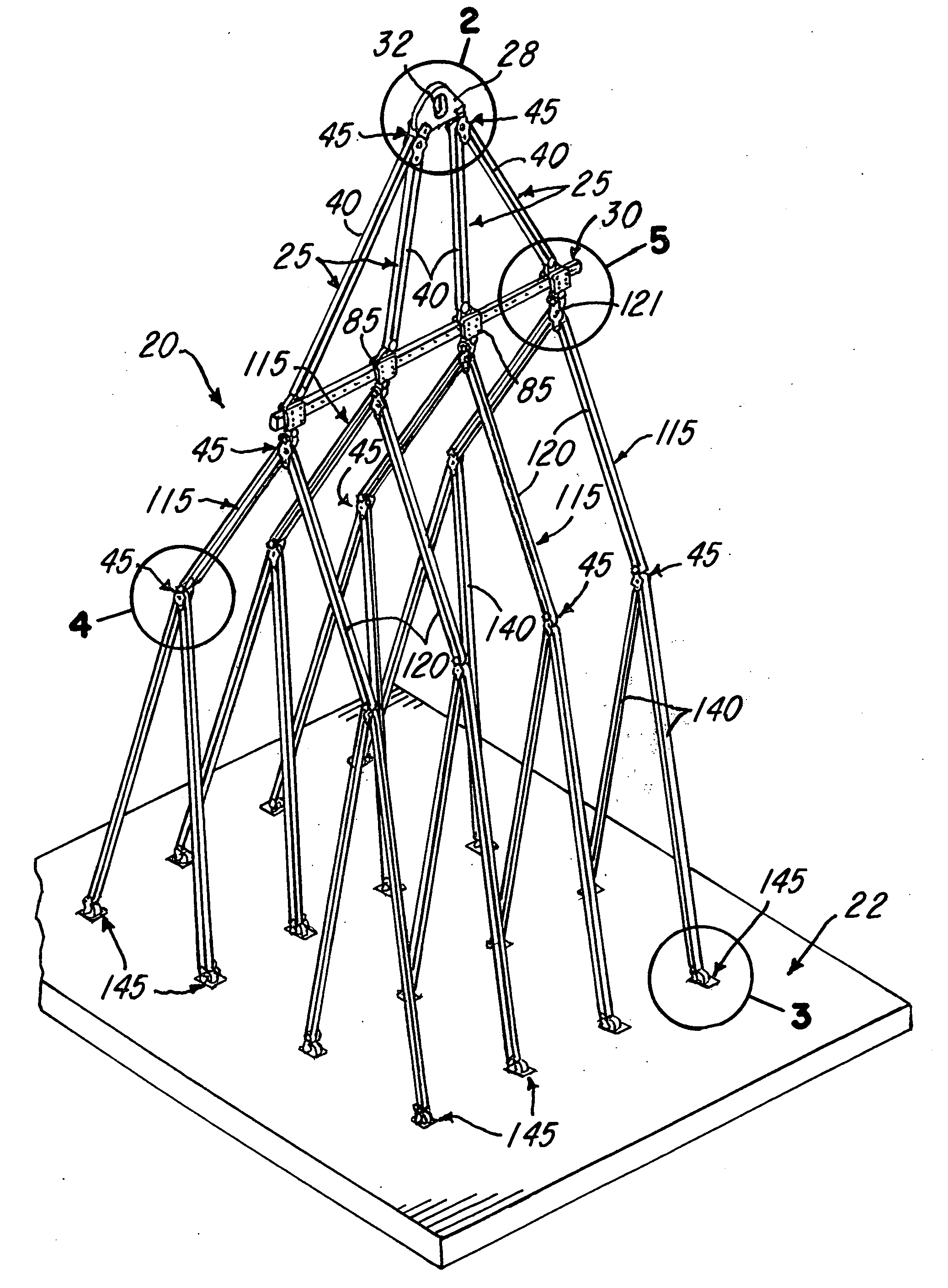
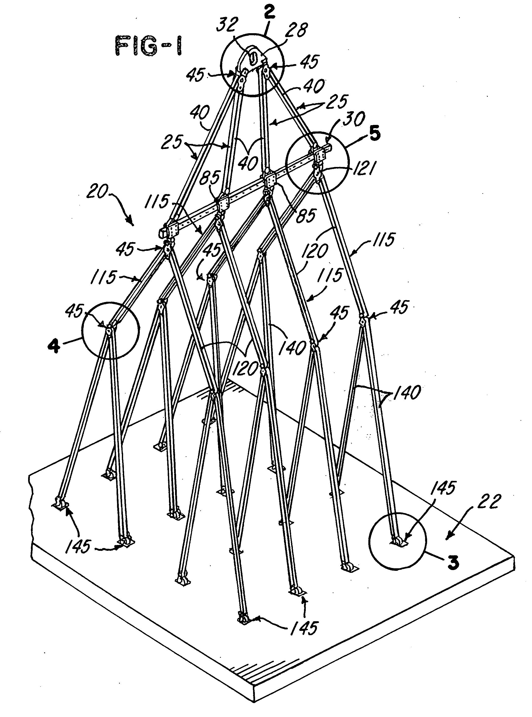
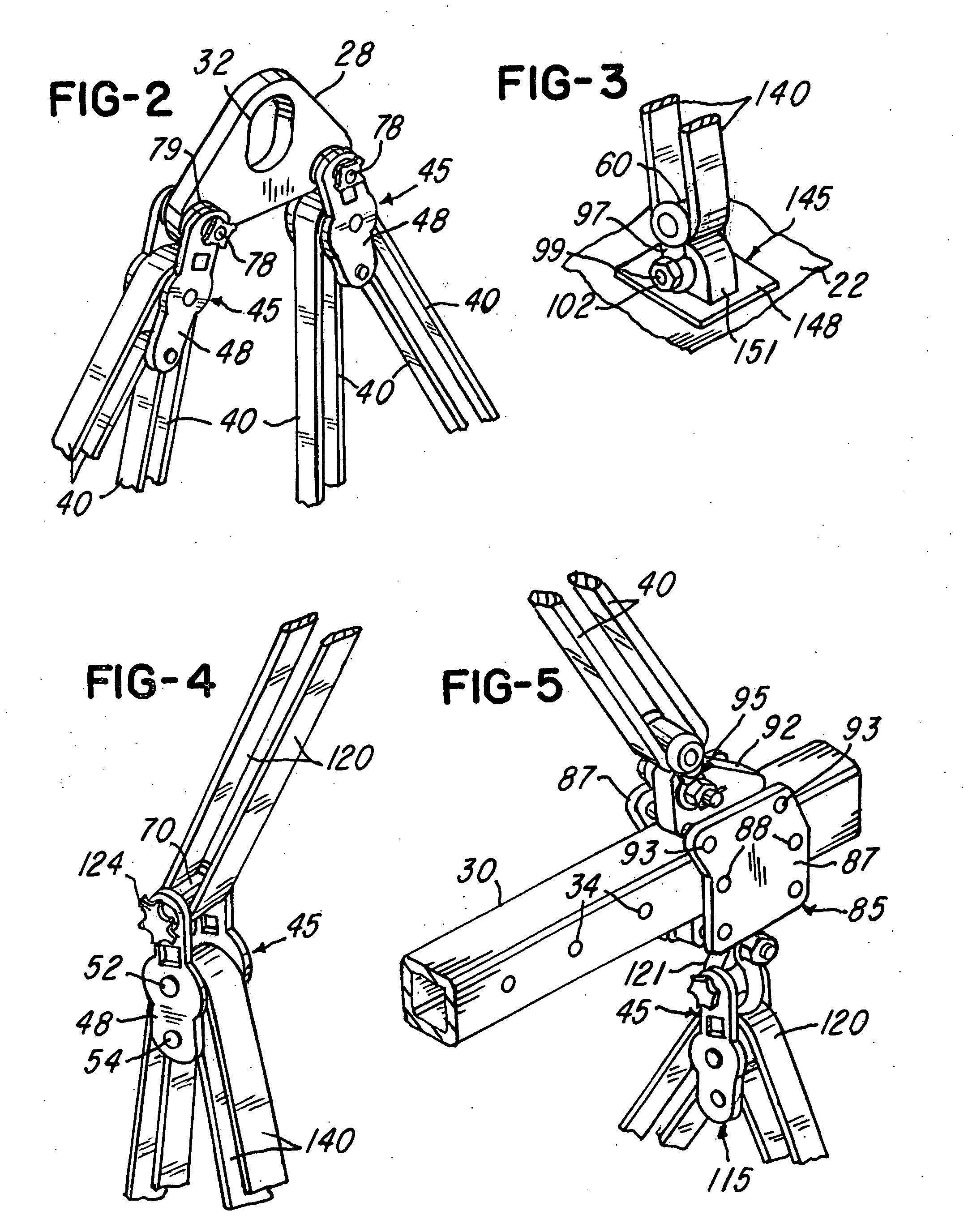
[0022]Referring to FIG. 1, a sling system 20 constructed in accordance with the invention is ideally suited for lifting, transporting and tilting a heavy object such as a horizontal reinforced concrete panel 22 which is commonly precast on a horizontal concrete floor and later lifted, tilted to a vertical position and positioned to form a wall panel for a single or multi-story tilt-up building. However, a sling system constructed in accordance with the invention may be used for lifting and maneuvering any form of heavy object with the aid of a lifting device such as a mobile crane. In accordance with the invention, a plurality of upper sling units 25 are used to connect an adaptor member or plate 28 to a horizontal elongated spreader beam 30. The adaptor plate 28 has a slot or opening 32 (FIG. 2) for receiving a crane hook (not shown), and the spreader beam 30 (FIG. 5) is preferably formed of square tubular metal or steel has horizontally spaced adjustment holes 34. Each of the slin...


PUM


Abstract

A sling system comprises a plurality of sling units each including a synthetic fibrous sling and a roller unit which has one or more spool-shaped rollers. The system provides for lifting a load in equilibrium and maintaining the load in that position or be rotated or tilted between horizontal and vertical positions. The system provides for a plurality of attachment points of the sling units to the load, and the sling units and may be set up as a single array or a multiple array depending on the type of load being lifted, transported and positioned. Endless and continuous loop synthetic slings and multiple roller units are used in sling units and provide for uniform and equal distribution of the load throughout the sling system. The spool-shaped rollers may be molded of a rigid plastics material with each roller having end flanges to confine the synthetic sling.

Description

BACKGROUND OF THE INVENTION[0001]When performing a lift in the hoisting and rigging industry, it is often desired that the load be in equilibrium so that each connection point at the load carry an equal part of the weight at all times to prevent overloading of the lifting components or prevent undesirable stresses on the load. In some applications, not only is it necessary to keep the load points in equilibrium, it is necessary to rotate or tilt the load from a horizontal position to a vertical position. Commonly, this task is accomplished by using wire rope or cable slings and large metal pulleys. In order to maintain the wire cable capacity, the ratio between the diameter and type of cable and the diameter of the pulley is referred to as a D / d ratio where “D” is the diameter of the pulley and the “d” is the diameter of the cable. By international standards for existing technology, this ratio ranges from 12-15. For example, a one inch diameter cable would require a pulley having a ...

Claims


Application Information

Patent Timeline
IPC IPC(8): B66C1/16B66C1/12
CPCB66C1/10B66C1/12B66C1/16B66C1/108
Inventor REGER, ROBERT J.
Owner REGER ROBERT J
Why Eureka
Try Eureka