Baby sling

a baby sling and sling body technology, applied in the field of baby slings, can solve the problems of user safety, slippage during use, etc., and achieve the effects of low elastic fabric, high reliability of knitting, and stable quality control

Inactive Publication Date: 2011-09-22
LUCKY IND
View PDF6 Cites 20 Cited by
  • Summary
  • Abstract
  • Description
  • Claims
  • Application Information

AI Technical Summary

Benefits of technology

[0040]According to the sixth aspect of the invention, the baby sling includes the infant holding part that both sides in the longitudinal direction of the annular body, which are formed of a low elastic knitted fabric, are knitted with a rib stitch and the center side in the longitudinal direction of the annular body, which is formed of a high elastic knitted fabric, is knitted with a plain stitch. The baby sling is therefore advantageous in that it is knitted with the rib stitch and the plain stitch that are generally highly reliable knitting, thereby providing a product which is stable in quality control, in addition to one of the effects of the first to the fifth aspects of the invention.
[0041]According to the seventh aspect of the invention, the baby sling includes the infant holding part, wherein both sides in the longitudinal direction of the annular body are formed of double sheets of a low elastic fabric. The baby sling is therefore advantageous in that elasticity in the longitudinal direction of the annular body is minimized as much as possible and the infant's buttocks can stably sink down in the baby sling, in addition to one of the effects of the first to the sixth aspect of the inv

Problems solved by technology

However, even if the baby sling is inserted into two rings to restrain therebetween, slippage may occur during use.
There

Method used


Image

  • Baby sling
  • Baby sling
  • Baby sling

Examples


first embodiment

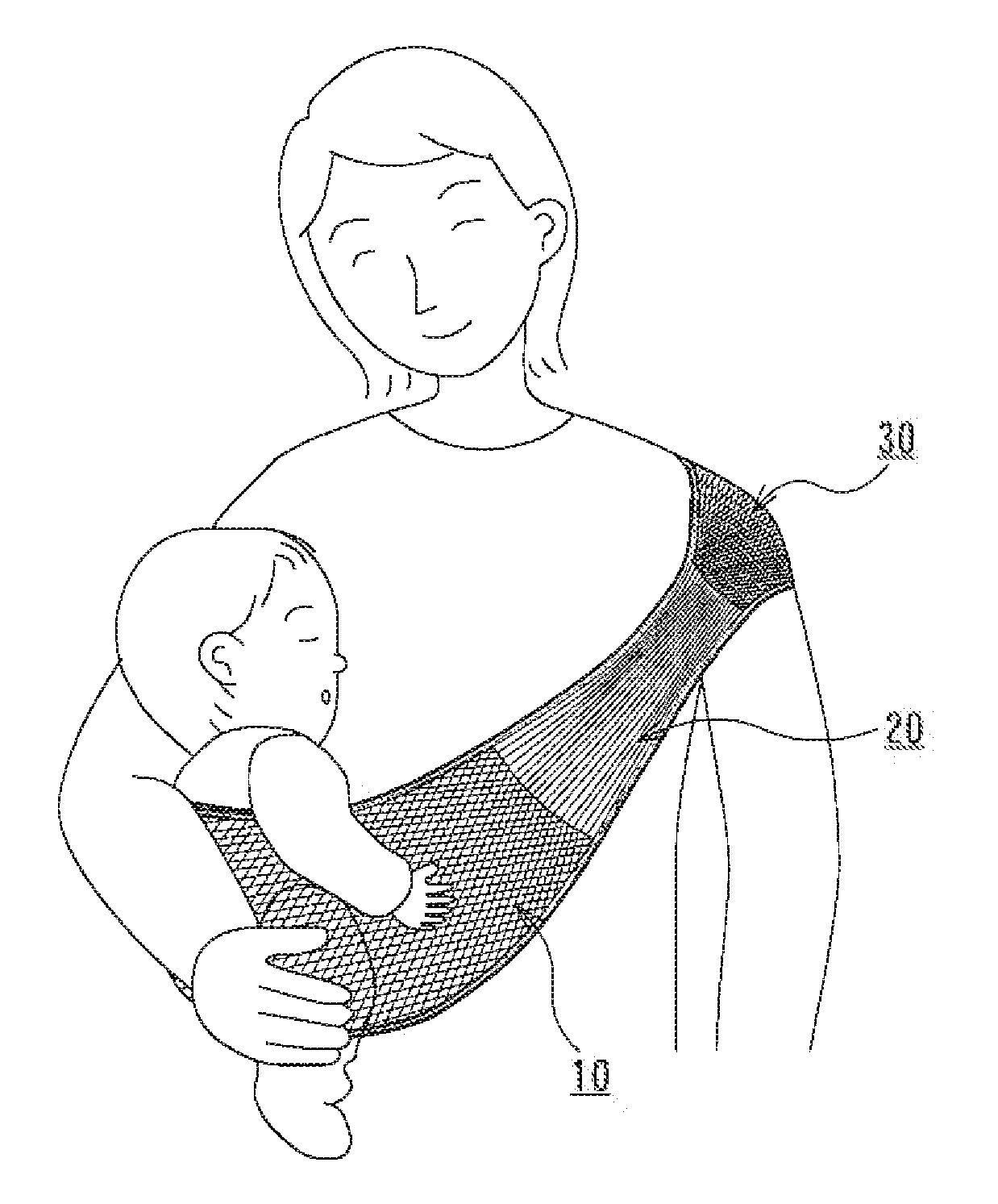
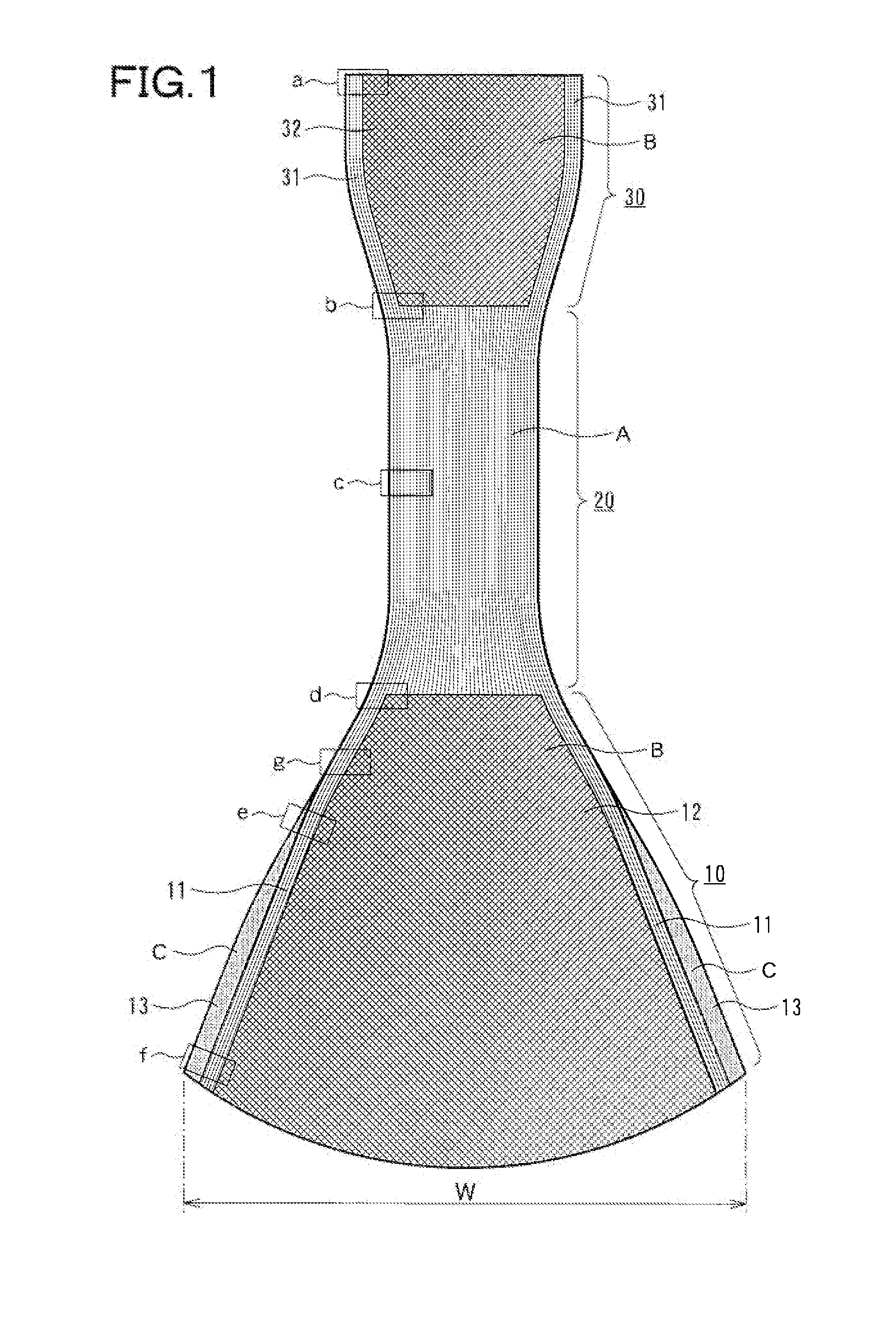
[0058]In FIG. 1, a baby sling according to an embodiment of the present invention includes an infant holding part 10, a belt part 20 and a shoulder pad part 30 integrally knitted together to form an annular shape.

[0059]The infant holding part 10 has a maximum width that corresponds to a central part in a longitudinal direction of an annular body and a gradually decrease in width between both sides in the longitudinal direction of an annular body toward both ends in the longitudinal direction of the annular body. In addition, both sides in the longitudinal direction of the annular body are formed of a knitted fabric “A” that has a low elasticity in the longitudinal direction of the annular body and includes an outer part 11 which is knitted with a rib stitch, also known as Japanese “gomuami”. The rib stitch that is applied to the outer part 11 is referred to as the Japanese “gomuami” or a fraise stitch also. There is no distinction between opposite surfaces of a knitted fabric thereo...

second embodiment

[0087]FIG. 12 shows a baby sling according to a second embodiment of the invention in which a shoulder pad part 30 has some increase in part of width in a width direction which is at right angle to a longitudinal direction of an annular body. The shoulder pad part 30 has the increased width which is longer than a width of a belt part 20 by 10 to 30%. Thereby, a burden on a shoulder of a person who carries an infant with the baby sling can be shared and reduced. Especially in the second embodiment shown in FIG. 12, the shoulder pad part 30 is an extension of the same rib stitch as the belt part 20. Therefore, workability may be improved.

[0088]In the baby sling according to the second embodiment of the invention, the shoulder pad part 30 has some increase in part of width in the width direction which is at right angle to the longitudinal direction of the annular body by 10 to 30% compared to the width of the belt part 20. However, an infant's body weight is about 10 kg. Thereby, the s...

third embodiment

[0103]FIG. 13 shows a baby sling according to a third embodiment of the invention. As shown in FIG. 13, a shoulder pad part 30 has a center that is curved upward to form a convex shape when the baby sling is folded in two so as to be at right angles to each other in a longitudinal direction of an annular body. In this case, as shown in FIG. 11a, when the curved convex-shaped portion is placed on a shoulder, to be precise when a concave part that is inside the convex-shaped portion is placed on the shoulder which has a convex shape, an infant's body weight can be a composition of vectors going from an upper side and a lateral side of the shoulder. Thereby, even a person who is likely to have a stiff shoulder can use it so that he or she is not likely to have the stiff shoulder. Moreover, it does not put a burden on an adjacent part of a neck. Therefore, the user's burden such as fatigue can be reduced.

[0104]Thus, the baby sling allows a burden on shoulder of a person who carries an i...


PUM


Abstract

A baby sling includes an infant holding part 10 that holds an infant in which the infant holding part 10 has a maximum width W that corresponds to a central part in a longitudinal direction of the baby sling and a gradually decrease in width between both sides in the longitudinal direction of the baby sling, wherein both sides in the longitudinal direction of the baby sling consists of outer parts 11 that are formed of a knitted fabric “A” which has a low elasticity in a width direction which is at right angle to the longitudinal direction of the baby sling and a center side in the longitudinal direction of the baby sling consists of an inner part 12 that is formed of a knitted fabric “B” which has a high elasticity in the width direction which is at right angle to the longitudinal direction of the baby sling. Thereby, the infant's body weight is applied to the inner part 12 that is formed of the high elastic knitted fabric “B” while both sides in the longitudinal direction of the baby sling are guarded with the outer part 11 that is formed of the low elastic knitted fabric “A”. Therefore, the baby sling can stably hold the infant. Accordingly, a safe and secure baby sling can be provided.

Description

BACKGROUND OF THE INVENTION[0001]1. Field of the Invention[0002]This invention relates to a baby sling that is used when carrying an infant as a supportive device to hold the infant.[0003]2. Description of the Related Art[0004]A conventional art of the kind mentioned above is described in Japanese Patent Laid Open No. 2007-75238. The Japanese Patent Laid Open No. 2007-75238 discloses a baby sling 1 that has an annularly formed belt body 10 in which the belt body 10 is formed of a knitted fabric that a central part 14 and side edge parts 15 are integrally knitted together using an elastic yarn for the central part 14 in a width direction and a non-elastic yarn for the side edge part 15. In addition, in the width direction of the belt body 10, the central part 14 is composed of a net tissue that is knitted into a relatively coarse net and the side edge part 15 is composed of a dense tissue that is knitted into a relatively fine net. The belt body 10 has also net tissues 13b and 13d th...

Claims


Application Information

Patent Timeline
IPC IPC(8): A47D13/02
CPCA47D13/02A47D13/025
Inventor HIGUCHI, JUNICHI
Owner LUCKY IND
Why Eureka
Try Eureka