Marine thruster with flow restraining rings

A technology of beam coils and propellers, which is applied in the direction of rotary propellers, can solve problems such as damage and low propulsion efficiency, and achieve the effect of avoiding friction or collision and improving propulsion efficiency

Inactive Publication Date: 2010-08-18
滕世成
View PDF0 Cites 1 Cited by
  • Summary
  • Abstract
  • Description
  • Claims
  • Application Information

AI Technical Summary

Problems solved by technology

[0003] Existing propellers generally use multi-bladed impeller propellers, because this kind of propeller will diverge the water flow being pushed along the normal direction of the propeller shaft when it rotates, greatly reducing the reaction force and making the propulsion efficiency lower; Although the efficiency of the propeller mechanism with a fixed shroud is improved, the blades will rub or collide with the fixed shroud due to the swing of the impeller, causing damage

Method used


Image

  • Marine thruster with flow restraining rings
  • Marine thruster with flow restraining rings

Examples


Embodiment Construction

[0009] Below in conjunction with accompanying drawing and embodiment the present invention is further described:

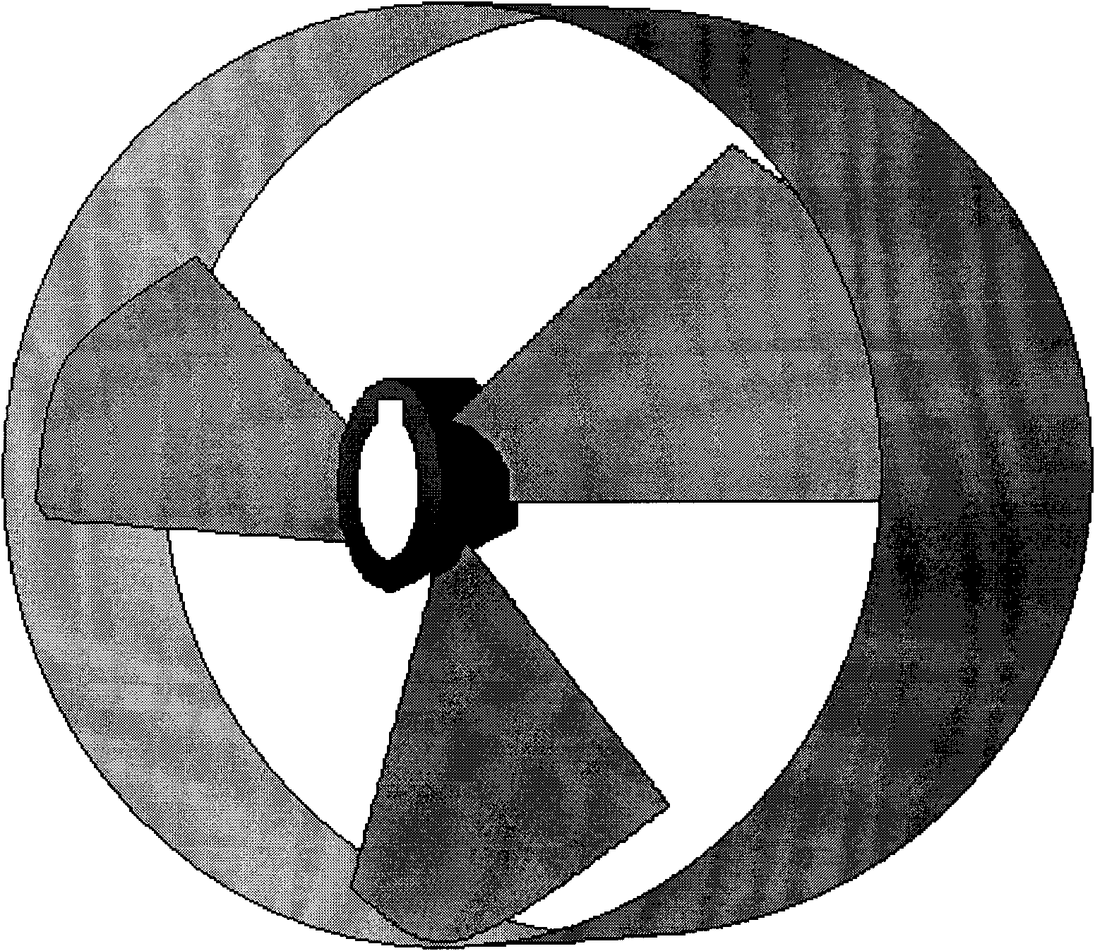
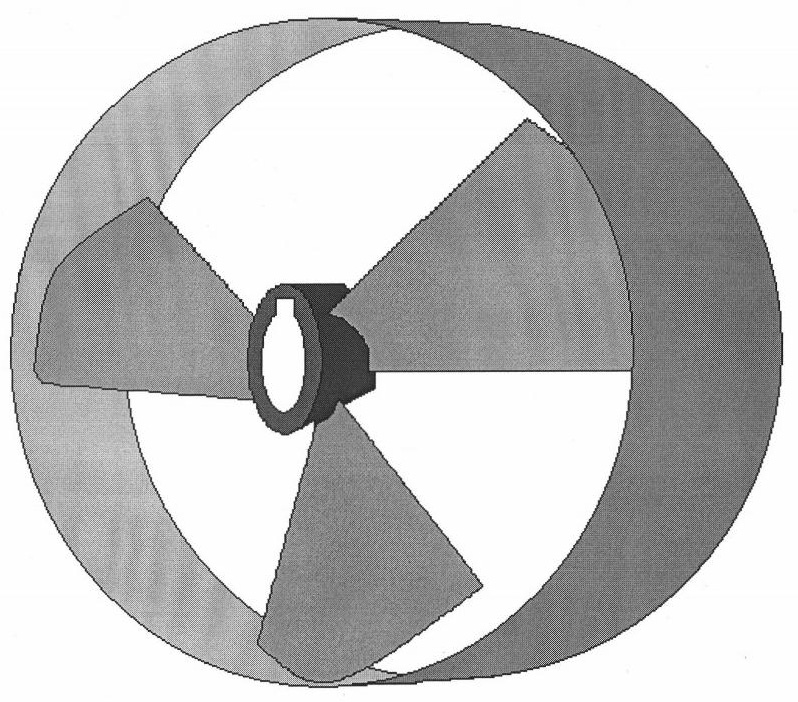
[0010] The blade pedicle (3) is provided with a keyway shaft hole (4) so ​​as to be connected with the power shaft of the ship; the blade pedicle (3) is connected with a propulsion blade (2), and the other end of the propulsion blade (2) is connected to the beam circle (1), in this way, when the power shaft of the ship pushes the blade pedicle (3) to rotate, the propulsion blade (2) and the beam coil (1) will rotate together, that is, the effect of beam current and flow diversion is achieved, and the propulsion efficiency is improved , avoiding the hazard of friction or collision between the blade and the fixed shroud when the existing propeller is working.


PUM


Abstract

The invention relates to a marine thruster, in particular to a marine thruster with a flow restraining ring, which is a novel marine thruster, a flow restraining rings and a thrusting vanes of which are connected together. The marine thruster achieves the effects of restraining and guiding flows and improving the thrusting efficiency and also prevents the harms of the friction or collision of the thrusting vanes and a fixed flow guiding shield.

Description

[0001] Field [0002] The invention relates to a marine propeller, in particular to a marine propeller with a choke ring. technical background [0003] Existing propellers generally use multi-bladed impeller propellers, because this kind of propeller will diverge the water flow being pushed along the normal direction of the propeller shaft when it rotates, greatly reducing the reaction force and making the propulsion efficiency lower; Although the efficiency of the propeller mechanism equipped with a fixed shroud is improved, the blades and the fixed shroud will be rubbed or collided due to the swing when the impeller rotates, causing damage. SUMMARY OF THE INVENTION [0004] In order to overcome the above-mentioned defects, the present invention proposes a new type of marine propeller that connects the beam coil and the propulsion blades together, which achieves the effect of beam flow, flow diversion, and improved propulsion efficiency, and avoids the need for propulsion b...

Claims


Application Information

Patent Timeline
Patent Type & Authority Applications(China)
IPC IPC(8): B63H1/12
Inventor 滕世成
Owner 滕世成
Why Eureka
Try Eureka