Lead seal structure of electric energy meter

A technology of electric energy meter and lead sealing, which is applied in the field of electric energy meter, can solve the problems of unfavorable automatic production, complex process of lead sealing, low efficiency of lead sealing, etc., and achieve the effect of simple structure, simple structure of lead seal and high production efficiency

Active Publication Date: 2012-06-27
董强
View PDF0 Cites 0 Cited by
  • Summary
  • Abstract
  • Description
  • Claims
  • Application Information

AI Technical Summary

Problems solved by technology

[0002] In order to prevent the electric energy meter from being opened at will, the traditional electric energy meter adopts figure 1 In the lead seal structure shown, screw holes (not shown in the figure) and wire holes are provided on the upper cover 1 of the electric energy meter, and threaded columns (not shown in the figure) are provided in the base 2 of the electric energy meter. Pass the lead seal screw 3-1 with a threading hole through the screw hole of the upper cover 1 and connect it with the threaded column of the base 2 so that the upper cover 1 and the base 2 are connected and fixed, and then pass the lead seal wire 5 through the upper cover 1 respectively The wire passing hole and the threading hole of the lead seal screw 3-1, and finally the two ends of the lead seal line 5 are closed and fixed by the lead seal block 4. Since the lead seal screw 3-1 has a threading hole, it needs a lead seal wire, which makes its cost higher, and the process of lead sealing is complicated, and the efficiency of lead sealing is low, which is not conducive to automatic production. Therefore, the lead seal structure of this traditional electric energy meter has the following disadvantages: complex structure, high cost, and low production efficiency , Not conducive to automated production

Method used


Image

  • Lead seal structure of electric energy meter
  • Lead seal structure of electric energy meter
  • Lead seal structure of electric energy meter

Examples


Embodiment

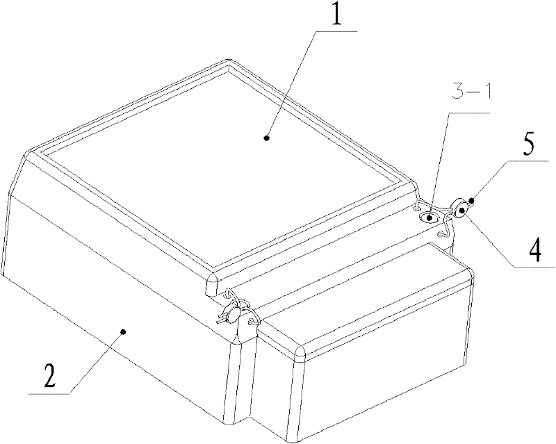
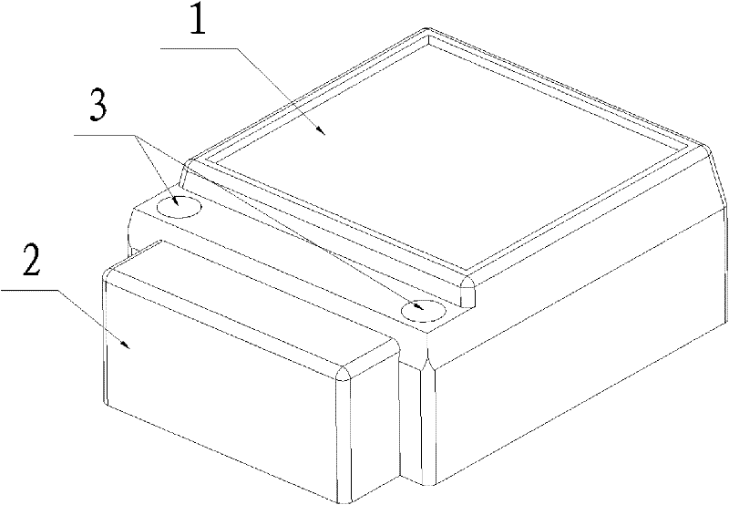
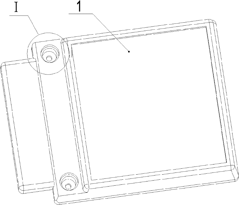
[0021] Such as figure 2 image 3 The lead seal structure of the electric energy meter shown has a base 2, and an upper cover 1 is connected to the base 2, and a seal screw 3 is used between the base and the upper cover to make the two packaged and connected, and the upper cover 1 is provided with a groove Body 11, screw holes 12 are provided at the bottom of the tank body, and lead sealing screws 3 are arranged in the screw holes.

[0022] Such as Figure 4 Image 6 As shown, the lead sealing screw 3 is composed of the connecting screw 6 and the lead sealing structure A connected thereto. The head of the connecting screw 6 has a radial annular groove 61; the lead seal structure A includes a chuck 8, a chuck 7 connected to the chuck, a bar code disc 9 installed on the chuck, and a bar code is placed in the bar code disc. , there is a cover 10 on the barcode disc; the chuck 8 is a circular disc body that matches the diameter of the groove body 11 of the upper cover 1, and t...


PUM


Abstract

The invention discloses a lead seal structure of an electric energy meter. The lead seal structure of the electric energy meter is characterized by comprising a base, an upper cover is connected to the upside of the base, the base and the upper cover are connected and packaged by using lead seal screws, the upper cover is provided with a trough body, and screw holes are arranged at the bottom of the trough body and are internally provided with the lead seal screws; the lead seal screws are formed by combining the lead seal structure of coupling screws; the head of the coupling screw is provided with a radial annular trough; the lead seal structure comprises a clamping chuck, a clamping column and a bar code disk, wherein the clamping column is connected to the clamping chuck, the bar codedisk is mounted on the clamping chuck, bar codes are placed in the bar code disk, and the bar code disk is provided with a sealing cover. When in mounting, the lead seal structure is firstly mounted,i.e. the clamping column is inserted into a trough-shape hole of the clamping chuck, the bar code disk and the sealing cover are fixedly connected by using wave-soldering respectively, the lead seal structure is pressed into the trough body, and the lead seal structure and the upper cover are inserted into the annular trough of the coupling screw through a bayonet on the clamping column. The invention has simple structure, high production efficiency and low cost.

Description

technical field [0001] The invention relates to an electric energy meter, in particular to a lead seal for the electric energy meter. Background technique [0002] In order to prevent the electric energy meter from being opened at will, the traditional electric energy meter adopts figure 1 In the lead seal structure shown, screw holes (not shown in the figure) and wire holes are provided on the upper cover 1 of the electric energy meter, and threaded columns (not shown in the figure) are provided in the base 2 of the electric energy meter. Pass the lead seal screw 3-1 with a threading hole through the screw hole of the upper cover 1 and connect it with the threaded column of the base 2 so that the upper cover 1 and the base 2 are connected and fixed, and then pass the lead seal wire 5 through the upper cover 1 respectively The wire passing hole and the threading hole of the lead seal screw 3-1, and finally the two ends of the lead seal line 5 are closed and fixed by the lea...

Claims


Application Information

Patent Timeline
Patent Type & Authority Patents(China)
IPC IPC(8): G01R11/24
Inventor 董强
Owner 董强
Why Eureka
Try Eureka