Optical fiber field connector

A connector and optical fiber technology, applied in the field of optical fiber field connectors and their installation components, can solve problems such as non-reusable, scrapped hot-melt protective sleeves, and reduced connection quality.

Inactive Publication Date: 2010-08-18
FENGHUO COMM SCI & TECH CO LTD
View PDF5 Cites 39 Cited by
  • Summary
  • Abstract
  • Description
  • Claims
  • Application Information

AI Technical Summary

Problems solved by technology

[0005] 1) Equipment is expensive
Because the fusion splicer is a complex and high-precision equipment, it is expensive
[0006] 2) Higher requirements on the environment
Since the welding machine is relatively heavy and is also a precision equipment, it must be placed on a firm and vibration-free platform, so it cannot adapt to the construction in a narrow space such as a hoistway.
[0007] 3) poor applicability
The eccentricity, eccentricity, material, melting point, etc. of the optical fiber are all required when the fusion splicer is fused. The difference in the variety and quality of the optical fiber will reduce the success rate of fusion
[0008] 4) The requirements for the operator are high, and the welding time is long
The requirements for the operation of the fusion splicing machine are very strict, and the operators must be trained in the early stage, and the operation time of the fusion splicing is relatively long
[0009] 5) Cannot be reused
If the fusion splice fails, the optical fiber in the splice section can only be cut off, and the heat-melt protection sleeve is scrapped at the same time, which increases the cost of materials and construction time
[0010] 6) The ability to protect the optical fiber is poor
[0015] 1) Generally, it is formed at one time and basically cannot be reused
[0016] 2) It is impossible to visually observe the butt joint quality of the optical fiber
[0017] 3) There is no tail-end fiber locking device, so that in engineering construction and scheduling, external traction will cause a gap at the joint surface of the two optical fibers, resulting in a serious decline in connection quality
[0018] 4) The ability to protect the optical fiber is poor, and it cannot withstand large axial and lateral tension and pressure. When the external force exceeds a certain range, it is prone to large attenuation or even fiber breakage.
The end face of the fiber core of the unpolished connector may be extremely rough or the end

Method used


Image

  • Optical fiber field connector
  • Optical fiber field connector
  • Optical fiber field connector

Examples


Embodiment Construction

[0081] The present invention will be described in further detail below in conjunction with the accompanying drawings.

[0082] While the invention is susceptible to various changes and substitutions, details thereof have been shown by way of example in the drawings and will be described in detail hereinafter. It should be understood, however, that the intention is not to limit the invention to the particular embodiments described. On the contrary, the intention is to cover all modifications, equivalents, and alternatives falling within the scope of the invention as defined by the appended claims.

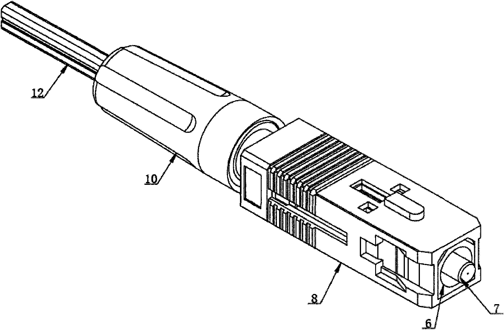
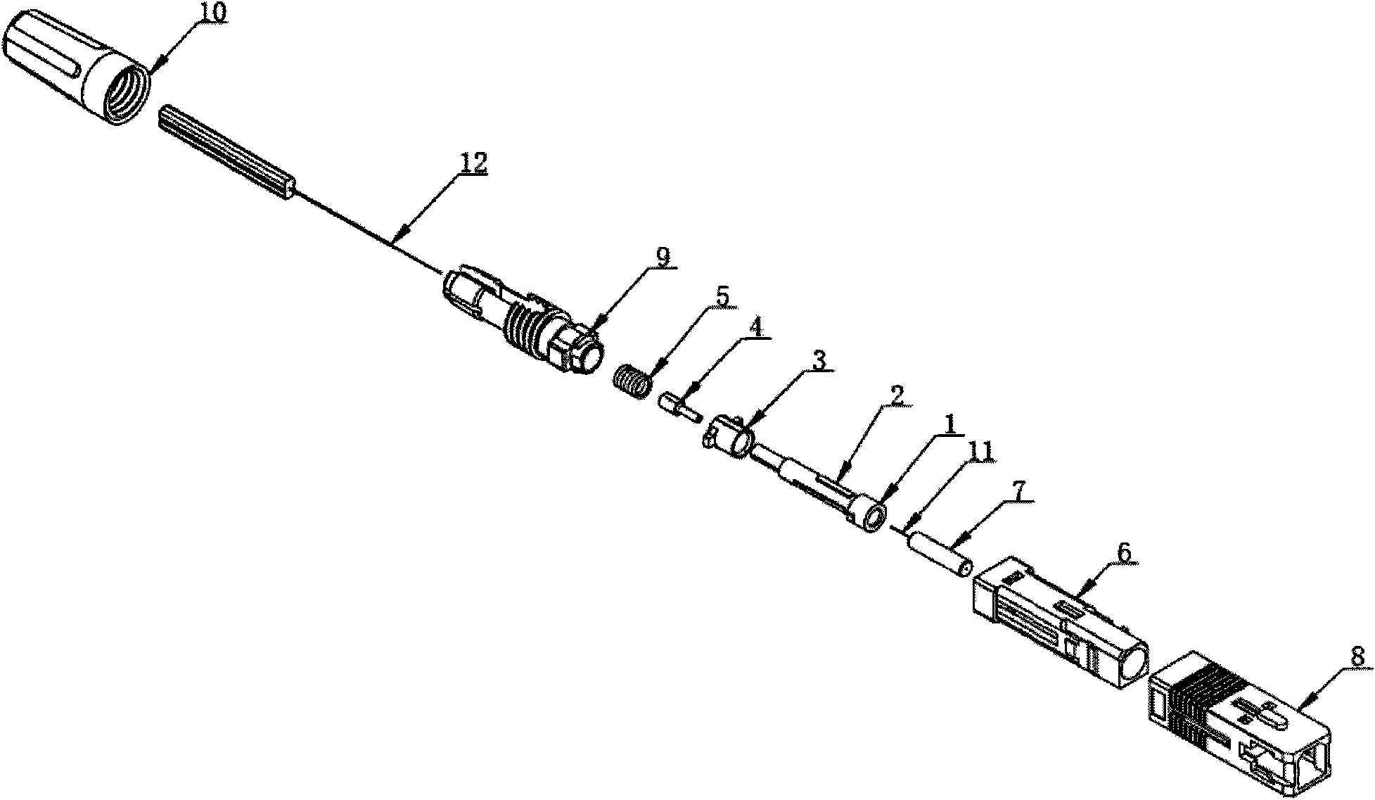
[0083] The invention relates to an optical fiber field connector. Specifically, the fiber optic field connector is capable of direct field termination. Assembly time during field termination can also be reduced by using simple mounting components as described in this article. For fiber-to-the-home (FTTH) network installations, the exemplary connectors described herein are simple ...


PUM


Abstract

The invention relates to an optical fiber field connector. A dismountable sleeve bin is sleeved outside a main body; the main body and the dismountable sleeve bin are provided with standard type interfaces; the main body is in a hollow structure; an optical fiber core insert is arranged at the front end of the main body; a preset optical fiber is arranged in the optical fiber core insert; a tail sleeve is arranged at the back end of the optical fiber core insert; a mechanical joint consisting of a substrate, a splint and a lantern ring is arranged in the main body; the front end of the mechanical joint is abutted with the optical fiber core insert, and the back end of the mechanical joint is connected with the tail sleeve through a guiding device and a damping device; a second optical fiber is arranged in the tail sleeve; and an outer protecting sleeve adopts a rotary screw thread structure to clamp the tail sleeve to prevent the second optical fiber from falling off and sliding. In the optical fiber field connector of the invention, the second tail end of the preset optical fiber is connected with the second optical fiber, a connection protecting box is not needed, storage protection for a bare optical fiber is unnecessary, when the optical fiber field connector is assembled, a special tool and grinding are not needed, whether the connection is successful can be detected at the field, and after installation, the field connector can be repeatedly opened for use.

Description

technical field [0001] The invention relates to a connector in an optical fiber transmission system, in particular to an optical fiber field connector, especially an optical fiber field connector suitable for on-site installation and an installation component thereof. Background technique [0002] Optical fiber has been widely used in various application scenarios in the telecommunications industry. The nearly unlimited bandwidth potential of optical fiber makes it an ideal medium for comprehensively carrying various services, gradually replacing the previous coaxial cable. With the large-scale application of FTTH (fiber-to-the-home), it is inevitable that a large number of optical fiber docking scenarios will appear. Compared with copper cables, fiber optic cable materials are very cheap, but if you use traditional methods to connect optical fibers, the cost is much higher than the cost of copper cable connections. For example, high-cost active fusion splicing equipment i...

Claims


Application Information

Patent Timeline
IPC IPC(8): G02B6/38
Inventor 程淑玲杨涛王世伟朱丽丽黄美金达庆杨军怀徐峰管汉章苏超
Owner FENGHUO COMM SCI & TECH CO LTD
Why Eureka
Try Eureka