

Rotary work head assembly
A technology of rotating working and working heads, which is applied in the direction of machine parts, applications, couplings, etc., which can solve the problems of increased weight of working heads, difficulty in accessing and operating the locking mechanism, and increased cost of working heads
- Summary
- Abstract
- Description
- Claims
- Application Information
AI Technical Summary
Problems solved by technology
Method used
Image

Examples
Embodiment Construction
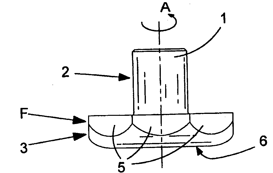
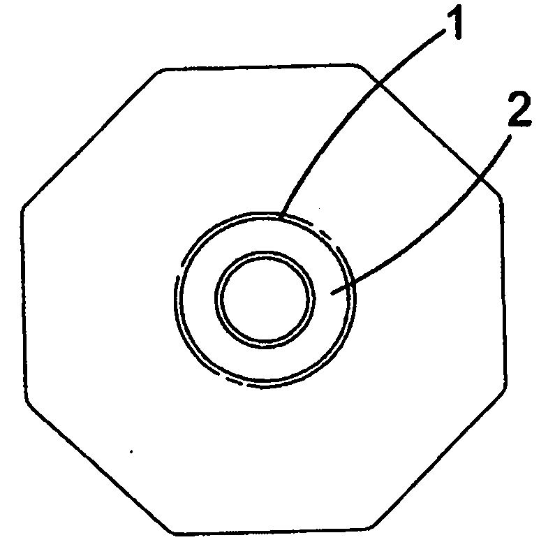
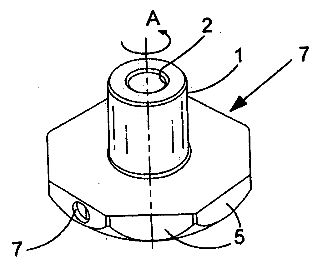
[0044] The drive hub 1 is collectively identified with the reference numeral 1 in FIGS. 1 a to 1 c. The hub is made from a single piece of machined metal. The hub has an upper part 2 (formed as a tube ring). The collar defines a bore for receiving a drive shaft (not shown) driven by the motor. Locking means (not shown) are securely provided for securing the hub to the drive shaft for co-rotation. Suitable locking means are known to those skilled in the art and may include, for example, dog stubs (not shown). The lower part 3 of the hub forms a generally dome-shaped cover. The side regions of the cover are machined with eight vertical planes 5 which provide an octagonal shape. Thus, the cap has an upper shoulder surface of a substantially octagonal ring extending around the upstanding tubular member. The lower surface of the cover is formed as a flat circular surface 6 . The peripheral area of this surface 6 tapers according to a domed profile which extends until it int...
PUM
 Abstract
Description
Claims
Application Information