Control of the display background illumination in a power switch

A technology for background lighting and circuit breakers, which is used in circuits, switchgear status indication, user interface regulations, etc., and can solve problems such as investment and maintenance costs.

Inactive Publication Date: 2010-08-18
SIEMENS AG
View PDF0 Cites 8 Cited by
  • Summary
  • Abstract
  • Description
  • Claims
  • Application Information

AI Technical Summary

Problems solved by technology

However, this results in an additional investment for providing a suitable, independent power supply at the location where the circ

Method used


Image

  • Control of the display background illumination in a power switch
  • Control of the display background illumination in a power switch
  • Control of the display background illumination in a power switch

Examples


Embodiment Construction

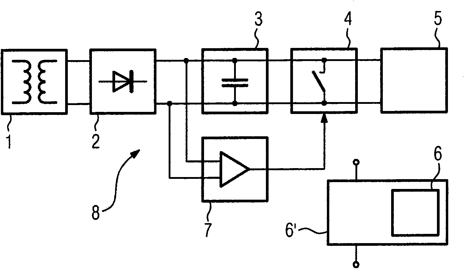
[0023] figure 1 A schematic view of a conventional low-voltage circuit breaker 8 with display devices 6, 6' can be seen in the technical background.

[0024] A current transformer 1 used as a current sensor utilizes its primary coil, for example connected to the grid to be monitored (not shown) and provides in its secondary coil a current proportional to the primary grid by means of an electromagnetic coupling, preferably via an iron core. A current that decreases in amperage. Furthermore, the reduced secondary current is converted in the rectifier unit 2 into a proportional, rectified direct current and in this form is simultaneously supplied to the other circuit parts of the circuit breaker 8 as their power supply and as Measure the signal. The connected storage capacitor 3 receives a charge proportional to its capacitance and the applied voltage and keeps this charge as a supply reserve. Because the current in the network to be monitored is subject to large fluctuations,...


PUM


Abstract

The invention relates to a power switch having an electronic overcurrent protection trigger, which receives the power supply thereof from the power supply network monitored by the power switch, comprising a current sensor, a rectifier, a storage capacitor, and a short-circuit switch, a disconnection unit, a measuring device for measuring the operating parameters of the power supply network to be monitored, an electronic circuit which processes the detected measured values, at least one electromagnetic trigger, controlled by the disconnection unit, for triggering the current-conducting power contacts of the power switch, and an electronic display device for representing the detected and/or processed measured values. It is provided that the display device (6) of the power switch acquires the power supply thereof from the power supply network monitored by the power switch, and an electronic device (10) powered with voltage from the power supply network monitored by the power switch controls the turning on and off of the background illumination (6) of the electronic display device (6), which obtains the voltage supply thereof from the power supply network monitored by the power switch, with the aid of an electronically controllable switch (9) as a function of the measured values detected in a measuring device of the electronic device (10). The invention further relates to a method for controlling the turning on and off of the background illumination of a display device of a power switch.

Description

technical field [0001] The invention relates to an electromechanical circuit breaker, in particular a low-voltage circuit breaker, with an overcurrent release, which circuit breaker is equipped with a display for displaying operating parameters, characteristic values ​​and fault signals, as stated in the preamble of claim 1 as defined in . Background technique [0002] The grid consists of a high-voltage grid and branched low-voltage grids which reach voltage values ​​of approximately 1000 V in the case of alternating current and 1500 V in the case of direct current. Low-voltage circuit breakers with electronic overcurrent protection releases are known, which are described in the English abbreviation ACB (air circuit breaker) as so-called normally open (offene) circuit breakers. Another similar device is a normally closed (geschlossener) circuit breaker or integral circuit breaker, whose English abbreviation is MCCB (molded case circuit breaker). The low-voltage circuit br...

Claims


Application Information

Patent Timeline
IPC IPC(8): H01H71/04H01H9/16H02H1/06
CPCH01H2071/006H01H9/161H01H71/04
Inventor 约尔格·布劳内埃德尔特劳德·穆西奥尔安德烈亚斯·潘克曼弗雷德·席勒托马斯·德里霍恩伊尔卡·雅库博夫斯基
Owner SIEMENS AG
Why Eureka
Try Eureka