
Membrane filter board compression molding device and molding method

A technology of molding and diaphragm filter plates, which is applied to household components, household appliances, and other household appliances. It can solve the problems of uneven force on the filter plate, bending deformation, seepage of the diaphragm and the filter plate, etc., and achieve reliable sealing. The effect of convenient thickness

Active Publication Date: 2015-04-01
杭州兴源环保设备有限公司
View PDF2 Cites 0 Cited by
  • Summary
  • Abstract
  • Description
  • Claims
  • Application Information

AI Technical Summary

Problems solved by technology

Its disadvantages: when the mold is closed, due to the uneven force on the filter plate, it is easy to bend and deform, which directly affects the sealing reliability between the diaphragm and the filter plate, and it is easy to seep and leak between the diaphragm and the filter plate during use.

Method used


Image

  • Membrane filter board compression molding device and molding method

Examples


Embodiment 1

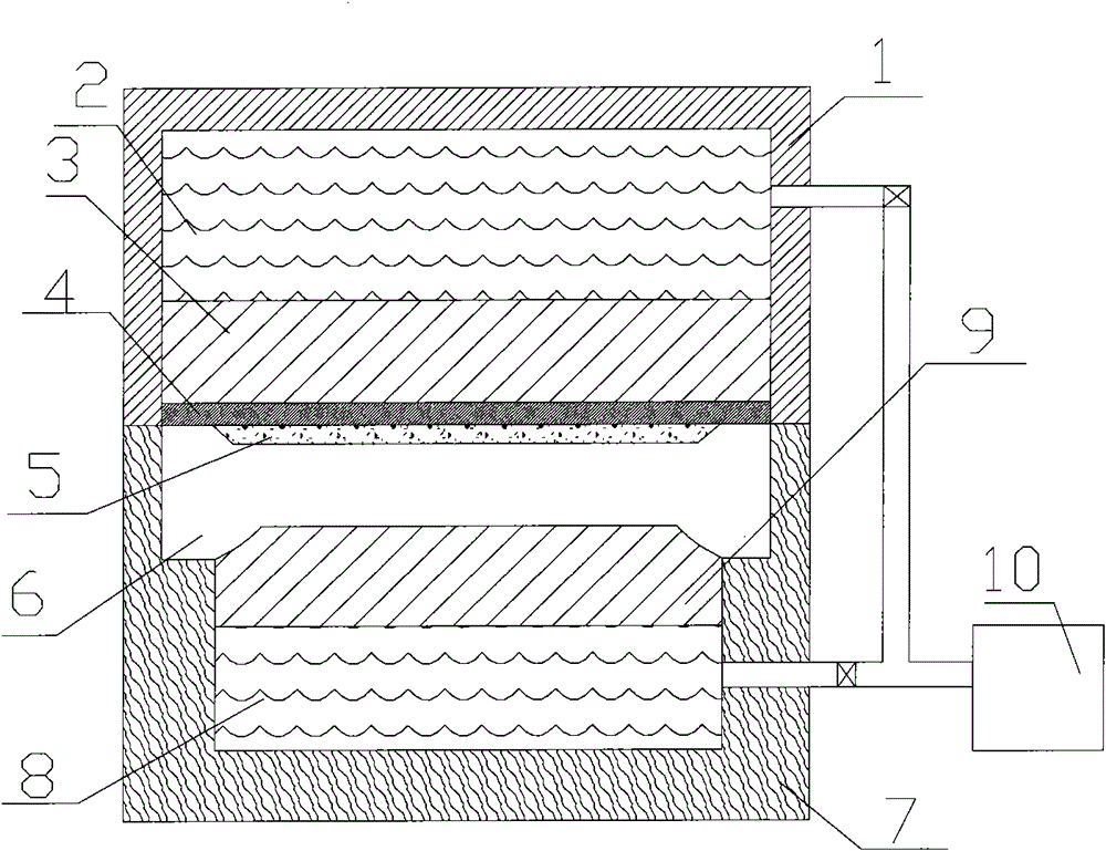
[0009] Example 1: refer to the attached figure 1 . Diaphragm filter plate molding device, which includes an upper mold and a lower mold, the upper mold is a cylinder type upper mold 1, and the mold cavity 4 of the cylinder type upper mold 1 is a diaphragm molding cavity, and the molding surface 3 of the diaphragm molding cavity is the cylinder piston surface. And the oil cylinder piston is located in the upper mold oil cavity 2; the lower mold 7 is composed of a filter plate 6 and a lower mold oil cylinder, one side of the filter plate 6 is in contact with the piston 9 in the lower mold oil cylinder, and the other side is the lower mold surface; The upper die oil cavity 2 and the piston cavity 8 are communicated with the hydraulic station 10 through an oil delivery pipe. The periphery of the filter plate 6 is in contact with the table surface of the support boss of the cylinder wall of the lower die cylinder. The face of the piston 9 matches the face of the filter plate 6 lo...

Embodiment 2

[0010] Embodiment 2: Diaphragm filter plate molding method, one side of filter plate 6 is put into the table surface of the support boss of the lower die oil cylinder wall, the lower die oil cylinder works and the surface of the piston 9 in the lower die oil cylinder is in phase with the groove surface of the filter plate. Touch, put the degradable mold core 5 on the other side of the filter plate, and then put the plastic mass on the degradable contact mold core 5. At this time, the cylinder-type upper mold 1 is instructed to move down, and the heated plastic mass is pressed. It is combined on the other side of the filter plate 6, and after cooling, a single-sided plastic membrane filter plate is formed. The degradable mold core 5 is paper or hydrolyzed material or hydrolyzed mold release agent. The pressures between the piston 13 and the piston 9 are equal.


PUM


Abstract

The invention relates to a membrane filter board compression molding device and a molding method. The device comprises an upper mold and a lower mold, wherein the upper mold is an oil cylinder type upper mold, the mold cavity of the upper mold is a membrane molding cavity, and the molding surface of the membrane molding cavity is an oil cylinder piston which is positioned in an upper mold oil cavity; the lower mold comprises a filter board and a lower mold oil cylinder, one side of the filter board contacts with the surface of the piston in the oil cylinder, and the other side is the mold surface of the lower mold; and the upper mold oil cavity and a piston cavity are communicated with a hydraulic station through an oil pipe. The device has the advantages that both sides of the filter board are stressed equally, when the membrane is pressed by the upper mold, the membrane can not generate bending deformation, and the reliable seal between the membrane and the filter board is ensured; liquid seepage and leakage between the membrane and the filter board can not occur; and the thickness of the membrane can be conveniently controlled by adjusting the piston in the lower mold oil cylinder.

Description

technical field [0001] The invention relates to a diaphragm filter plate molding device and a molding method for directly molding a diaphragm on a filter plate surface, and belongs to the field of diaphragm filter plate manufacturing. Background technique [0002] CN101249703, titled "molded diaphragm filter plate and molding method", the invention is a structure and molding method of directly molding the diaphragm on the surface of the filter plate core, which includes a filter plate core, and the filter plate core is placed in a lower mold frame Inside, a degradable mold core is placed on the tympanic surface of the filter plate core, and then the plastic mass is placed on one side of the tympanic membrane surface of the filter plate core, and then the upper mold and the lower mold frame are closed. Integrated single-sided plastic diaphragm filter plate, then turn the single-sided filter plate and put it into the lower mold frame, place a degradable mold core on the tympan...

Claims


Application Information

Patent Timeline
Patent Type & Authority Patents(China)
IPC IPC(8): B29C43/18B29C43/36B29C33/52B29C33/58B29L31/14
Inventor 周立武徐孝雅
Owner 杭州兴源环保设备有限公司
Learn More