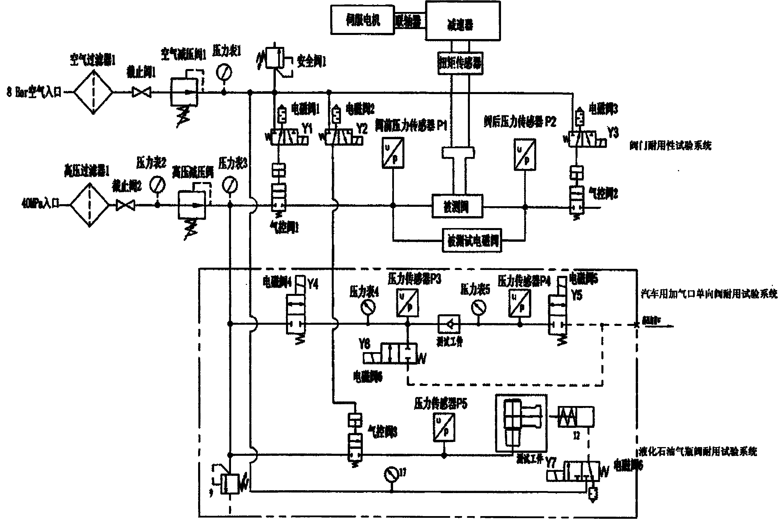
Automatic control valve life tester
A technology for automatic control of valves and life tests, applied in the testing of machines/structural components, by measuring the increase and decrease rates of fluids, measuring devices, etc., to achieve the effects of ensuring safety, increasing the frequency of experiments, and improving the response speed
Inactive Publication Date: 2010-08-25
SHANGHAI INST OF SPECIAL EQUIP INSPECTION & TECHN RES
View PDF5 Cites 18 Cited by
- Summary
- Abstract
- Description
- Claims
- Application Information
AI Technical Summary
Problems solved by technology
Whether it is the user, the valve manufacturer or the testing organization, if they want to understand and master the reliability of the valve quality in a short period of time, they must rely on the valve life test device. However, there is no ideal device for testing it at present.
Method used
View moreImage
Smart ImageViewing Examples
Examples
Embodiment Construction
Login to View More PUM
 Abstract
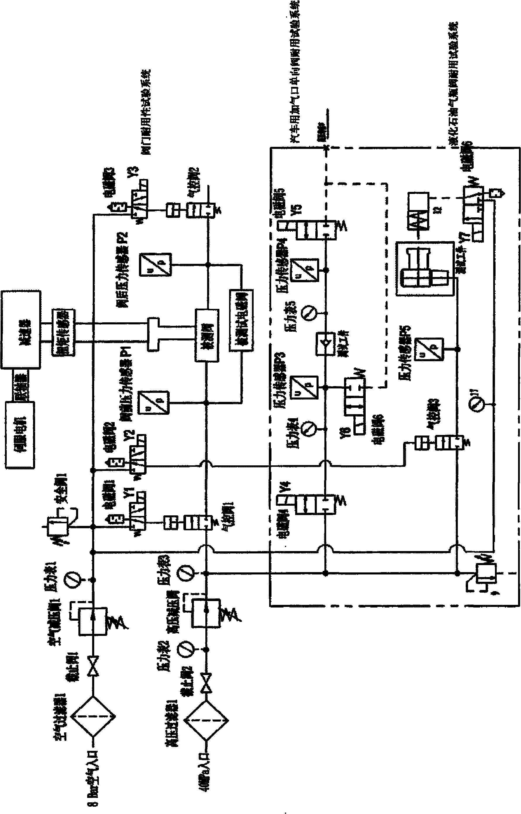
The invention relates to an automatic control valve life tester, which mainly comprises a control system and a durability tester, wherein the durability tester comprises a valve durability testing system, an automotive gas charging-port one-way valve durability testing system and a liquefied petroleum gas cylinder self-closing device durability testing system. The tester is mainly used for the test of the opening and closing of a valve and the total travel torque and the durability tests of a self-closing device, an automotive gas charging port one-way valve and a liquefied petroleum gas cylinder. The three systems in the durability tester are positioned in the same frame and independent of one another and controlled by different software interfaces. When the automatic control valve life tester is used for testing the life of the valve, the test can be completed quickly, numerical values such as the pressure, the time and the test times are displayed in the test process, the test result can be stored automatically and also can be printed, and the test result can automatically stored after power is cut off.
Description
technical field The invention relates to the field of valve durability testing, in particular to an automatic control valve life testing machine. Background technique Valve life is an important indicator of valve quality and reliability assessment. At present, there are more than 4,000 valve factories in my country. When the wear between the valve plate and the valve seat reaches a certain level, the valve will leak beyond the standard after it is closed. Therefore, many products will not expose quality problems in a short period of time. After a period of use, their quality defects will appear. Whether users, valve manufacturers or testing organizations want to understand and master the reliability of valve quality in a short period of time, they must rely on valve life test devices. However, there is no ideal device for testing them. Contents of the invention The technical problem to be solved by the present invention is to provide an automatic control valve life testi...
Claims
Login to View More Application Information
Patent Timeline
 IPC IPC(8): G01M19/00G01M3/28G01M99/00
Inventor 徐维普杨金富罗晓明袁弈雯吴俭
Owner SHANGHAI INST OF SPECIAL EQUIP INSPECTION & TECHN RES
Features
- R&D
- Intellectual Property
- Life Sciences
- Materials
- Tech Scout
- Unparalleled Data Quality
- Higher Quality Content
- 60% Fewer Hallucinations
Learn More Browse by: Latest US Patents, China's latest patents, Technical Efficacy Thesaurus, Application Domain, Technology Topic, Popular Technical Reports.
© 2025 PatSnap. All rights reserved.Legal|Privacy policy|Modern Slavery Act Transparency Statement|Sitemap|About US| Contact US: help@patsnap.com


