Method for collecting surface wave and creeping wave of ultrasonic flaw detector

A calibration method and ultrasonic technology, applied in the direction of material analysis, instruments, scientific instruments, etc. using sonic/ultrasonic/infrasonic waves, can solve problems such as increasing factory production costs, defect positioning errors, etc., to extend service life, reduce production costs, Simple and reliable method

Inactive Publication Date: 2010-08-25
符丰
View PDF2 Cites 13 Cited by
  • Summary
  • Abstract
  • Description
  • Claims
  • Application Information

AI Technical Summary

Problems solved by technology

At this time, in order to obtain the actual distance of the workpiece defect, flaw detectors can only manually calibrate and calculate the defect position according to the data provided by the probe manufacturer. The value of the internal sound path and the front edge of the probe will change. After such a situation occurs, because other instruments cannot automatically detect

Method used


Image

  • Method for collecting surface wave and creeping wave of ultrasonic flaw detector
  • Method for collecting surface wave and creeping wave of ultrasonic flaw detector

Examples


Embodiment Construction

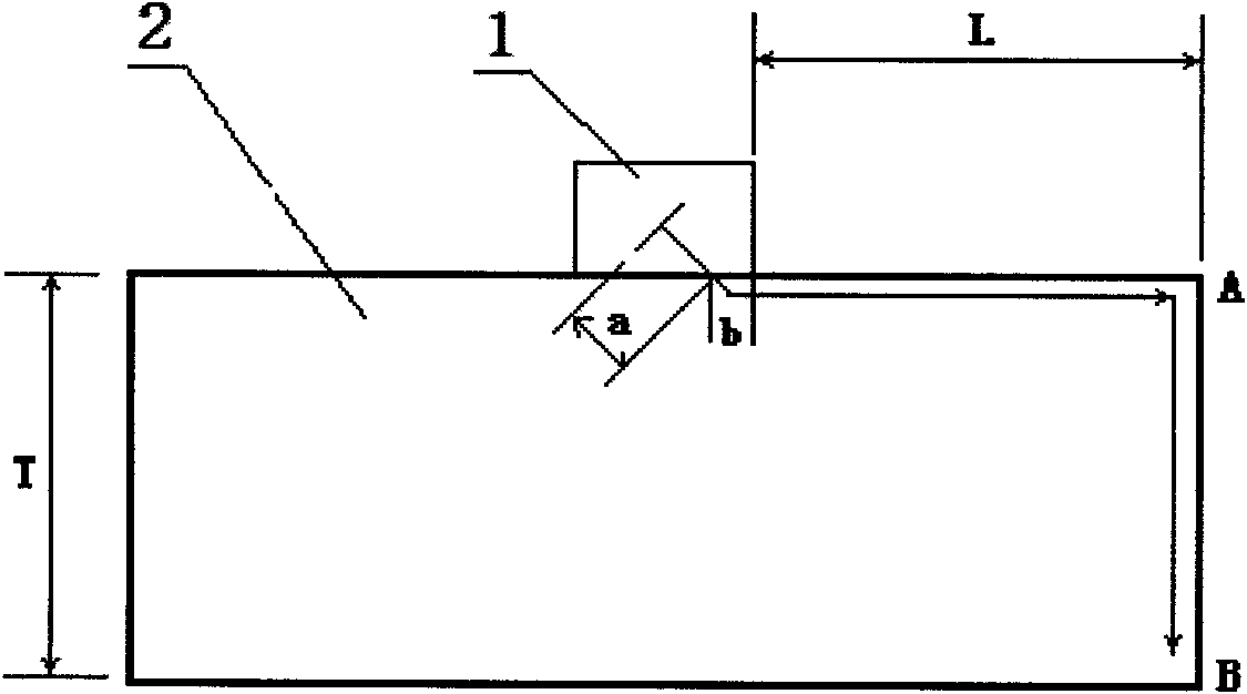
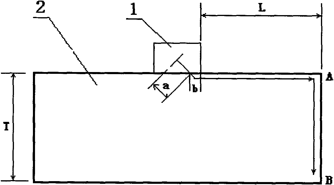
[0011] As an embodiment of the present invention, as shown in Figure 1, a surface wave and creeping wave calibration method for an ultrasonic flaw detector includes an ultrasonic flaw detector, which transmits ultrasonic waves through a probe to detect workpiece flaws, and the distance of workpiece defects obtained by the detection is The sum of the actual distance and the calibration distance, wherein the calibration distance is the sum of the sound path a that the ultrasonic wave travels inside the probe, and the sound path b that the ultrasonic wave propagates on the workpiece surface but is covered by the probe shell. The method includes the following steps in sequence:

[0012] 1) Prepare a standard test block 2 for probe calibration, such as various commercially available standard test blocks such as CSK-IA type, and a surface wave or creeping wave probe 1 for ultrasonic flaw detectors;

[0013] 2) Use the probe 1 to move back and forth on the test block 2 until the surfa...


PUM


Abstract

The invention discloses a method for collecting a surface wave and a creeping wave of an ultrasonic flaw detector, relating to an apparatus collecting method. The apparatus comprises an ultrasonic flaw detector which detects the flaw of a work piece by transmitting the ultrasonic wave through a probe head, wherein the detected distance of the flaw of the work piece is the sum of practical distance and corrected distance. The method sequentially comprises the following steps of: preparing a standard test block for correcting the probe head, and the surface wave or the creeping wave probe head for the ultrasonic flaw detector; leading the probe head to move on the test block back and forth till that the ultrasonic flaw detector displays that the surface wave and the creeping wave generate highest reflected wave at the flaw of the standard test block so as to obtain the distance S from an ultrasonic wave-transmitting end in the probe head to the flaw; detecting the distance L from the headmost end of the probe head to the flaw; and subtracting L from S to obtain the correcting distance for correcting ultrasonic flaw detector. The method fills in gap that the existing ultrasonic flaw detector is difficult to correct the front edge of the transverse wave (the surface wave and the creeping wave) probe head and the route of the ultrasonic wave in the probe head.

Description

technical field [0001] The invention relates to an instrument calibration method, in particular to a surface wave and creeping wave calibration method for an ultrasonic flaw detector. Background technique [0002] At present, when ultrasonic flaw detectors are used for surface wave or creeping wave flaw detection of workpiece defects, ultrasonic waves are emitted through the probe to detect workpiece flaws. The detected workpiece defect distance is the sum of the actual distance and the calibration distance, where the calibration distance is the ultrasonic wave in the probe. The sum of the sound path a traveled by the interior and the sound path b that the ultrasonic wave propagates on the surface of the workpiece but is covered by the probe shell. At this time, in order to obtain the actual distance of the workpiece defect, the flaw detector can only calculate the flaw position according to the data provided by the probe manufacturer. The value of the internal sound path a...

Claims


Application Information

Patent Timeline
IPC IPC(8): G01N29/30
Inventor 符丰
Owner 符丰
Why Eureka
Try Eureka