Induction heating cooker
A technology of induction heating and cooker, which is applied in induction heating, induction heating device, electric/magnetic/electromagnetic heating, etc., can solve the problem that the abnormal overheating of the pot cannot be detected, and achieve the effect of safety control
- Summary
- Abstract
- Description
- Claims
- Application Information
AI Technical Summary
Problems solved by technology
Method used
Image

Examples
Embodiment 1
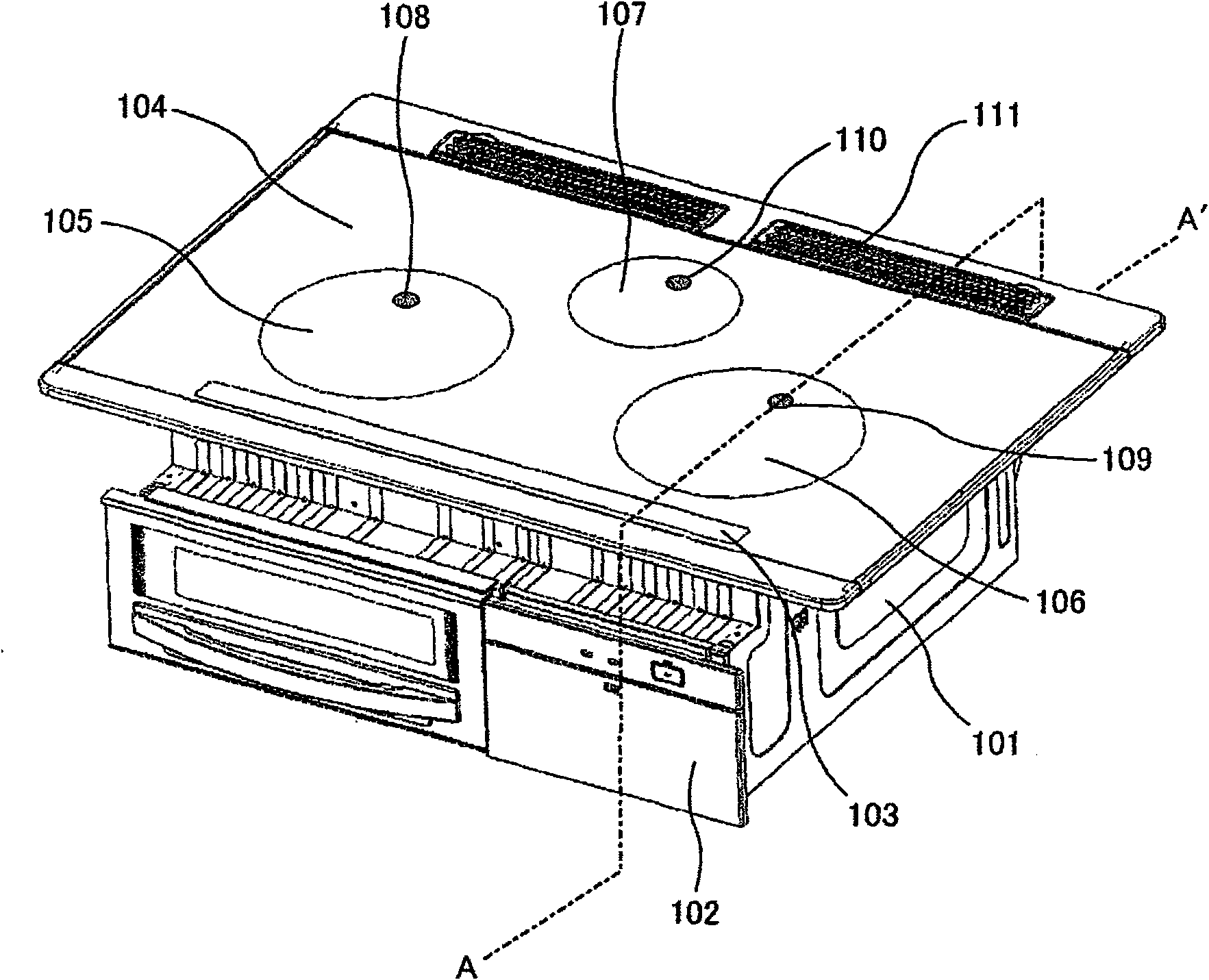
[0032] figure 1 It is an external perspective view of the induction heating cooker of Example 1. exist figure 1 Among them, symbol 101 is the main body of the induction heating cooker, symbol 102 is an operation part for turning on and off the power supply and heating setting, etc., symbol 103 is a display part, and symbol 104 is a placing pot formed of heat-resistant glass or the like. top plate and is penetrating in the infrared field. Reference numerals 105 and 106 indicate the heating area where a heating coil such as an induction heating pot is installed below, reference number 107 indicates a heating area where a large-end heater such as a heating pot is installed below, and reference numbers 108 to 110 indicate infrared rays that radiate from the bottom of the pot. In the infrared ray penetrating region penetrating below the top plate 104 , the mark 111 is a suction port for cooling air that cools the circuits and the like provided in the main body 101 .
[0033] f...
Embodiment 2
[0050] Next, Embodiment 2 of the present invention will be described. Among the configurations of the second embodiment, descriptions of the same configurations as those of the first embodiment are omitted.
[0051] The induction heating cooker of the second embodiment can observe the temperature of the bottom of the pan at multiple places by providing a plurality of detection areas of the infrared sensor module. Figure 12 It is a top view of the vicinity of the heating coil 200 located below the heating region 106 . Such as Figure 12 As shown, the induction heating cooker of this embodiment is equipped with the detection area 121 and the detection area 122 of the infrared sensor module, and can observe the temperature of the pan bottom on the detection area 121 and the detection area 122 .
[0052] Here, if the infrared sensor module 407 is installed at two places directly below the detection areas 121 and 122, it becomes as follows: Figure 4 The obstacles of the coolin...
Embodiment 3
[0060] Next, Embodiment 3 of the present invention will be described. Among the configurations of the third embodiment, descriptions of the same configurations as those of the second embodiment are omitted.
[0061] Figure 14 It is a sectional view of the induction heating cooker of Example 3. Such as Figure 14 As shown, prisms 141 and 142 are provided under the top plate 104 . The infrared rays passing through the detection area 121 of the top plate 104 reach the infrared sensor module 407 through the prism 141 . Likewise, the infrared rays penetrating the detection area 122 of the top plate 104 reach the infrared sensor module 407 through the prism 142 . Compared with the structure of the embodiment 2, the structure of the embodiment 3 has fewer parts constituting the optical path, so in addition to the effect obtained by the structure of the embodiment 2, it has the advantage of being easy to manufacture.
[0062] In addition, in the induction heating cooker of Examp...
PUM
 Abstract
Description
Claims
Application Information
 - R&D Engineer
- R&D Manager
- IP Professional
- Industry Leading Data Capabilities
- Powerful AI technology
- Patent DNA Extraction
Browse by: Latest US Patents, China's latest patents, Technical Efficacy Thesaurus, Application Domain, Technology Topic.
© 2024 PatSnap. All rights reserved.Legal|Privacy policy|Modern Slavery Act Transparency Statement|Sitemap