Starch emulsion defoaming pump

A starch emulsion and defoaming technology, which is applied in the direction of pumps, pump components, non-variable pumps, etc., can solve the problems of low production efficiency of potato starch emulsion defoaming

Inactive Publication Date: 2010-09-01
温州市康而达实业有限公司
6 Cites 0 Cited by

AI-Extracted Technical Summary

Problems solved by technology

[0004] The technical problem to be solved by the present invention is to solve the...

Abstract

The invention discloses a starch emulsion defoaming pump which comprises a pump body. The pump body is provided with a first cavity and a second cavity which are respectively and internally provided with a primary impeller and a secondary impeller, the primary impeller is provided with an outer shell and a hub, six radial big blades are evenly arranged between the outer surface of the hub and the inner wall of the outer shell, the rotary central line of the big blades and the central line of the hub form a horizontal eccentric distance of 12.8mm and a vertical the eccentric distance of 1.8mm, the middle of each big blade is respectively provided with a small blade which forms an included angle of 125 degrees with the big blade, and the right end part of the outer shell is evenly provided with twelve subsidiary blades along the axial direction. The primary impeller is provided with the six big blades at inclined angles, a small blade is attached to each big blade, and the twelve subsidiary blades are arranged at the tail end of each big blade. When the starch emulsion defoaming pump is in use, deforming is firstly carried out by the big blades and the small blades attached to the big blades and then carried out by the subsidiary blades, therefore, the wheel defoaming rate reaches over 80 percent.

Application Domain

Pump componentsRadial flow pumps +2

Technology Topic

EmulsionImpeller +2

Image

  • Starch emulsion defoaming pump
  • Starch emulsion defoaming pump
  • Starch emulsion defoaming pump

Examples

  • Experimental program(1)

Example Embodiment

[0013] The present invention will be described in detail below in conjunction with the drawings.
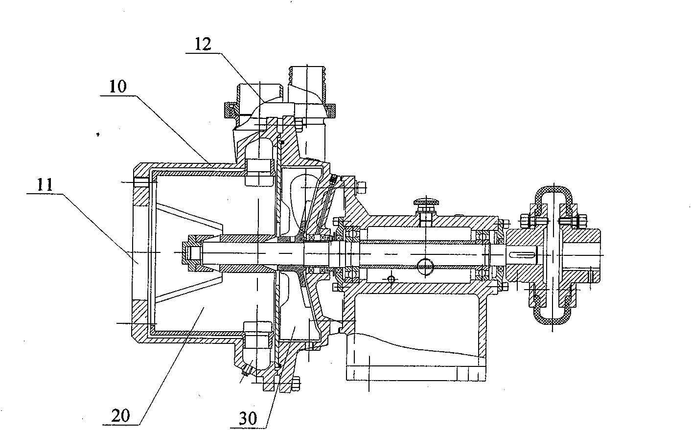
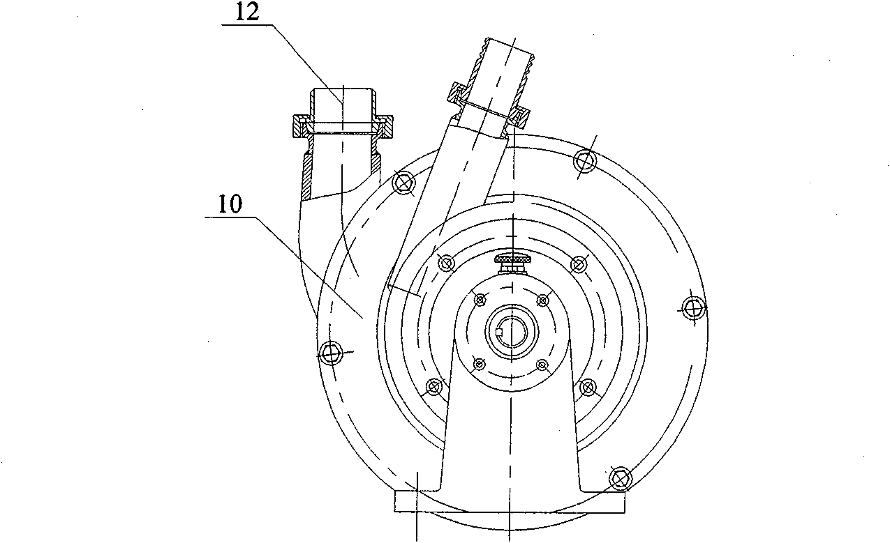
[0014] The invention provides a starch emulsion defoaming pump, which is used for defoaming potato starch emulsion. Its structure is like figure 1 , figure 2 As shown, it includes a pump body 10, a primary impeller 20, and a secondary impeller 30. The interior of the pump body 10 is sequentially provided with a first and a second chamber from left to right. The primary impeller 20 and the secondary impeller 30 are respectively Set in the first and second chambers, the front end of the pump body 10 is provided with a potato starch emulsion inlet 11 communicating with the first chamber, and the outer wall of the pump body 10 is provided with a potato starch emulsion leading to the first chamber Discharge port 12; the first-stage impeller 20 and the secondary impeller 30 are coaxially arranged on a pump shaft. With the rotation of the pump shaft, the first-stage impeller 20 sucks potato starch emulsion from the inlet 11 and defoams in the first chamber It is then discharged from the discharge port 12.
[0015] The first-stage impeller 20 of the present invention adopts a special structure, so the bubble breaking rate reaches more than 80%. Such as image 3 , Figure 4 As shown, the first-stage impeller has a cylindrical shell 1 and a hub 2. Six large radial blades 3 are evenly distributed between the outer surface of the hub 2 and the inner wall of the cylindrical shell 1. The horizontal eccentricity L1 between the centerline of rotation of the blade 3 and the centerline of the hub 2 is 12.8mm, and the vertical eccentricity L2 is 1.8mm; the middle of the large blade 3 is provided with small blades 5 protruding toward the centerline of rotation of the large blade. The included angle α between the small blade and the large blade is 125 degrees; the right end of the cylindrical shell 1 is uniformly provided with twelve sub blades 4 protruding toward the center line of rotation of the large blade along the axial direction. The axial length of the hub 2 is smaller than the axial length of the cylindrical casing 1 and the right end surface of the hub 2 is flush with the right end surface of the cylindrical casing 1.
[0016] The above embodiment is only a preferred embodiment of the present invention, in which the horizontal eccentricity L1 between the centerline of rotation of the large blade 3 and the centerline of the hub 2 is 10-15mm, the vertical eccentricity is 1.5-2.0mm, and the small blades The angle α of the large blades of 120-130 degrees can realize the technical solution of the present invention.
[0017] The present invention is not limited to the above-mentioned best embodiment. Anyone should know that structural changes made under the enlightenment of the present invention, and any technical solutions that are the same or similar to the present invention, fall within the protection scope of the present invention.

PUM

PropertyMeasurementUnit
Angle120.0 ~ 130.0deg

Description & Claims & Application Information

We can also present the details of the Description, Claims and Application information to help users get a comprehensive understanding of the technical details of the patent, such as background art, summary of invention, brief description of drawings, description of embodiments, and other original content. On the other hand, users can also determine the specific scope of protection of the technology through the list of claims; as well as understand the changes in the life cycle of the technology with the presentation of the patent timeline. Login to view more.
Why Eureka
Try Eureka