Pneumatic tire

A technology of pneumatic tires, tires, applied in tire parts, tire tread/tread pattern, transportation and packaging, etc., to achieve the effect of improving edge effect, improving drainage, and improving performance on ice

Active Publication Date: 2010-09-01
THE YOKOHAMA RUBBER CO LTD
View PDF1 Cites 0 Cited by
  • Summary
  • Abstract
  • Description
  • Claims
  • Application Information

AI Technical Summary

Problems solved by technology

[0004] However, in recent years, it is required to further improve the on-ice performance of new products, and the current situation is that sufficient on-ice performance cannot always be obtained with conventional thin grooves.

Method used


Image

  • Pneumatic tire
  • Pneumatic tire
  • Pneumatic tire

Examples


Embodiment

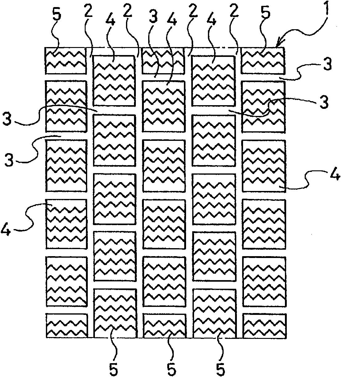
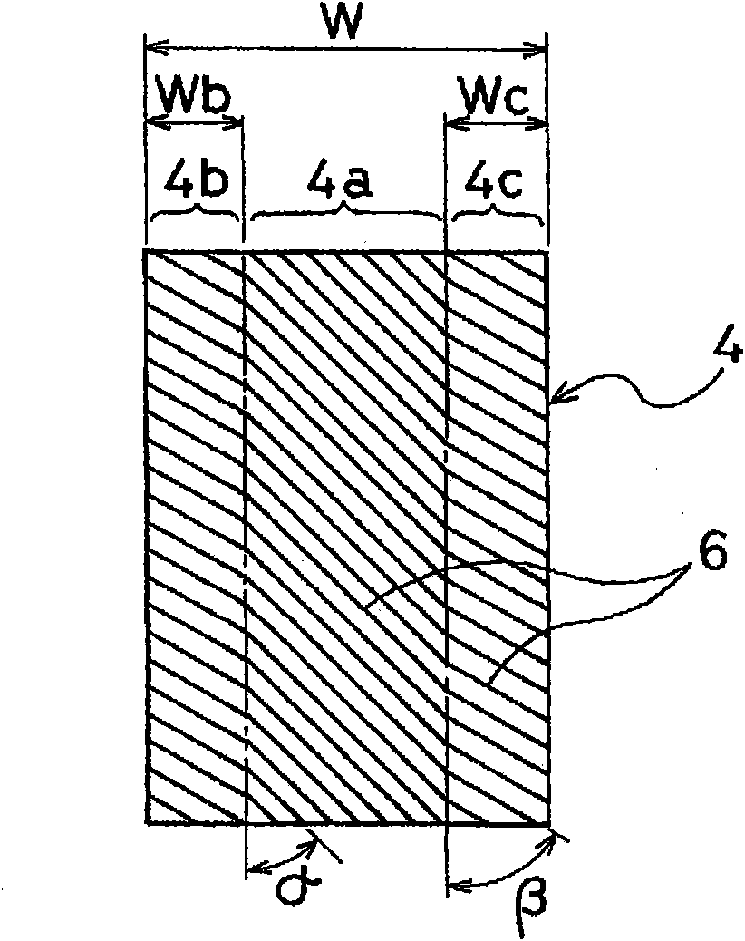
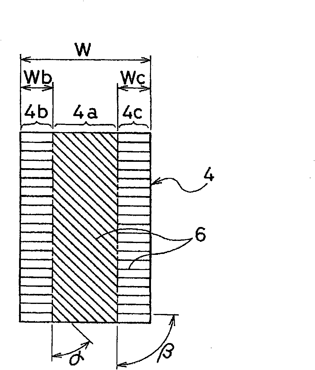
[0031] Tires of Conventional Example 1 and Examples 1 to 10 were produced. The tires had a tire size of 195 / 65R15, and the tread portion was provided with a plurality of land portions (blocks) divided by grooves, and a plurality of grooves were respectively provided on these land portions. A pneumatic tire for icy and snowy roads with a sipe pattern and a plurality of thin grooves respectively provided on the contact surface of the land portion, wherein the inclination angle α (°) of the thin grooves in the central region of the land portion with respect to the tire circumferential direction, The inclination angle β (°) of the thin groove in the end region of the land portion with respect to the tire circumferential direction and the ratio (%) of the width of the end region to the width of the land portion are different as shown in Table 1. In Conventional Example 1 and Examples 1 to 10, the groove area ratio of the thin grooves in the land portion was set to 35%, the depth of ...


PUM


Abstract

A pneumatic tire having further improved ice performance achieved by narrow grooves. The pneumatic tire is provided, on a tread, with land sections partitioned by grooves, and each of the land sections is provided with narrow grooves in the ground contact surface of the land section. The angle of tilt of the narrow grooves relative to the tire's circumferential direction is set such that the angle is greater in end regions located on opposite sides of a center region, with respect to the tire's lateral direction, than in the center region.

Description

technical field [0001] The present invention relates to a pneumatic tire in which a thin groove is provided on a ground contact surface of a land portion, and more specifically, to a pneumatic tire capable of further enhancing the effect of improving the performance on ice by the thin groove. Background technique [0002] In all-weather tires and studless tires, a plurality of land portions composed of blocks and / or ribs are defined on the tread portion, and a plurality of sipes are formed on these land portions, respectively. In such a pneumatic tire, in order to exhibit sufficient on-ice performance when a new product that exhibits the original properties of rubber is not yet available, a plurality of thin grooves shallower than the sipe are provided on the ground contact surface of the land portion (for example, refer to Patent Document 1). [0003] The above-mentioned narrow grooves are generally arranged on the ground surface of the land portion at a constant pitch in ...

Claims


Application Information

Patent Timeline
Patent Type & Authority Applications(China)
IPC IPC(8): B60C11/00B60C11/12
CPCB60C2011/1231B60C11/12B60C11/1376Y10S152/03Y10S152/902
Inventor 桥本佳昌
Owner THE YOKOHAMA RUBBER CO LTD
Why Eureka
Try Eureka