Systems and methods employing coupling elements to increase antenna isolation

An antenna system and coupling element technology, applied to antenna combinations with different interactions, mid-position feed between antenna endpoints, antennas, etc., can solve problems such as expensive and complex three-dimensional structural shapes

Inactive Publication Date: 2010-09-01
HONG KONG APPLIED SCI & TECH RES INST
View PDF0 Cites 20 Cited by
  • Summary
  • Abstract
  • Description
  • Claims
  • Application Information

AI Technical Summary

Problems solved by technology

However, such systems are very expensive due to their complex three-dimensional structural shapes
Currently, no prior art system provides sufficient isolation with minimal complexity

Method used


Image

  • Systems and methods employing coupling elements to increase antenna isolation
  • Systems and methods employing coupling elements to increase antenna isolation
  • Systems and methods employing coupling elements to increase antenna isolation

Examples


Embodiment Construction

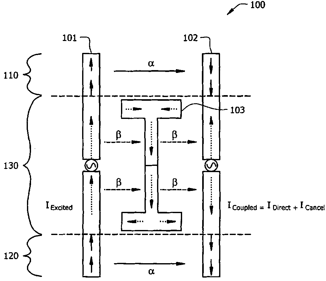
[0017] figure 1 A typical antenna system 100 for one embodiment of the invention is described. System 100 includes antenna elements 101 and 102 , and coupling element 103 . In this example, the antenna element 101 is driven by a radio frequency (RF) feed, and the current in the antenna element 101 is I Excited . In antenna element 102, the total current due to mutual coupling with antenna element 101 is I Coupled .

[0018] exist figure 1 There are three areas. Region 110 is the region where coupling element 103 is not located between antenna elements 101 and 102 . In other words, in region 110, each antenna element 101 and 102 is within line of sight of the other element. Region 120 is similar to region 110 . In region 130 , coupling element 103 is located between antenna elements 101 and 102 .

[0019] In regions 110 and 120 there is direct coupling between antenna elements 101 and 102 . In this example, the current caused by direct coupling is I Direct , which is...


PUM


Abstract

An antenna system comprises a first antenna element mutually coupled with a second antenna element, the mutual coupling between the first and second antenna elements causing a first current in the second antenna element, and a coupling element disposed at least partially between the first and second antenna elements, wherein the coupling element is mutually coupled to each of the first and secondantenna elements, and wherein the coupling element is configured to induce a second current in the second antenna element that at least partially cancels the first current.

Description

technical field [0001] The present invention relates generally to multi-element antennas, and more particularly to systems and methods for employing components to reduce the effects of mutual coupling between multiple antenna elements. Background of the invention [0002] As antenna systems become smaller, the space between antenna elements in these systems becomes more scarce. The space between antenna elements may affect not only the radiation pattern of the system, but also the mutual coupling between antenna elements. Mutual coupling is inductive / capacitive coupling between two or more antennas that can sometimes cause unwanted performance degradation by interfering with the signal being transmitted or by causing the antenna elements to emit unwanted signals. In general, the closer the two antenna elements are located, the higher the potential for mutual coupling. [0003] Therefore, modern antenna designers usually look for ways to reduce the coupling between antenna ...

Claims


Application Information

Patent Timeline
Patent Type & Authority Applications(China)
IPC IPC(8): H01Q1/52H01Q21/29
CPCH01Q9/16H01Q1/243H01Q9/42H01Q1/521
Inventor 麦志强柳江平麦志伦
Owner HONG KONG APPLIED SCI & TECH RES INST
Why Eureka
Try Eureka