Supercharge Your Innovation With Domain-Expert AI Agents!

Molding milling cutter and molding method

A technology for forming milling cutters and cutter bodies, applied in milling cutters, milling machine equipment, manufacturing tools, etc., can solve problems such as low work efficiency, reduced machining accuracy, and accumulation of machining errors.

Active Publication Date: 2012-08-29
SHENZHEN JINGJIANG YUNCHUANG TECH CO LTD
View PDF3 Cites 0 Cited by
  • Summary
  • Abstract
  • Description
  • Claims
  • Application Information

AI Technical Summary

Problems solved by technology

However, the above method needs to be processed twice, and the workpiece needs to be re-clamped or the position of the milling cutter adjusted. The work efficiency is low, and it is easy to cause the accumulation of processing errors and reduce the processing accuracy.

Method used


Image

  • Molding milling cutter and molding method
  • Molding milling cutter and molding method
  • Molding milling cutter and molding method

Examples


Embodiment Construction

[0013] The forming milling cutter and the forming method using the forming milling cutter of the present invention will be further described in detail below in conjunction with the accompanying drawings and embodiments.

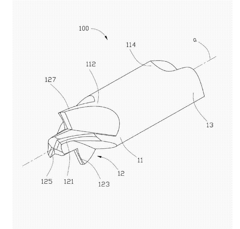
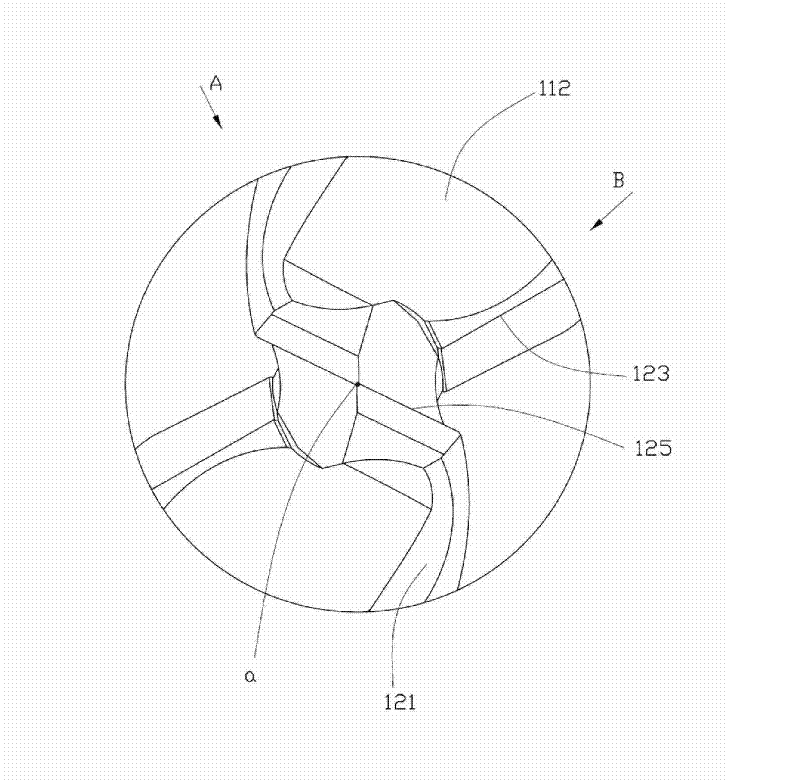
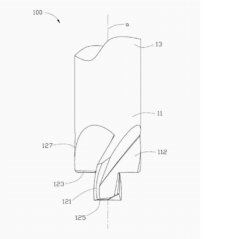
[0014] See figure 1 , the form milling cutter 100 of the embodiment of the present invention includes a cutter body 11 , a cutting portion 12 and a handle 13 .

[0015] The cutter body 11 is roughly cylindrical and has a rotation axis a. During processing, the form milling cutter 100 rotates around the rotation axis a, and the rotation axis a coincides with the central axis of the cutter body 11 . The cutter body 11 includes a front end 112 and a rear end 114 , the cutting portion 12 is formed on the front end 112 , and the handle 13 is formed on the rear end 114 .

[0016] The tool handle 13 can be in the form of a straight shank or a tapered shank, which is used for conveniently clamping the forming milling cutter 100 to the control device during processin...


PUM


Abstract

The invention relates to a molding milling cutter comprising a cutter body and a first cutting edge and a second cutting edge which are formed on the cutter body, wherein the first cutting edge and the second cutting edge are staggered in the rotating direction of the cutter body. A cutting face formed when the first cutting edge rotates a circle around the rotating axis of the cutter body insects with the second cutting edge. The invention also provides a method for processing by utilizing the molding milling cutter. The molding milling cutter and the molding method can form two surfaces thejoint of which is sharp-angled by one-time processing only. The invention has the advantages of higher processing efficiency and lower cost and is easy to ensure the processing precision.

Description

technical field [0001] The invention relates to a forming milling cutter and a forming method, in particular to a forming milling cutter and a forming method which can form two connected surfaces on a workpiece through one-time processing, and the joint of the two surfaces is a sharp angle . Background technique [0002] Form milling cutters are generally specially designed and manufactured for machining workpieces with specific shapes. They are usually used to process angled surfaces, groove surfaces, special-shaped holes and stepped surfaces, etc. The shape of the cutting edge of the form milling cutter is generally suitable for the shape of the workpiece Matching, in order to form the required specific shape on the workpiece through one-time processing. When it is necessary to process two connected surfaces on the workpiece, and the connection of the two surfaces is a sharp corner protruding outward, if the traditional method is used to design, that is, the cutting edge ...

Claims


Application Information

Patent Timeline
Patent Type & Authority Patents(China)
IPC IPC(8): B23C5/12
Inventor 徐龙
Owner SHENZHEN JINGJIANG YUNCHUANG TECH CO LTD
Features
  • R&D
  • Intellectual Property
  • Life Sciences
  • Materials
  • Tech Scout
  • Unparalleled Data Quality
  • Higher Quality Content
  • 60% Fewer Hallucinations
Learn More