Welding structure of small shaft and cover board of electronic expansion valve and electronic expansion valve

A technology of electronic expansion valve and welding structure, applied in the direction of valve operation/release device, valve lift, valve details, etc., can solve the problems of difficult welding positioning, low welding efficiency, inconvenient clamping, etc., and achieve shortening electrode discharge distance, Improve welding strength and solve the effect of insufficient strength

Active Publication Date: 2012-08-29
ZHEJIANG DUNAN HETIAN METAL CO LTD
View PDF7 Cites 0 Cited by
  • Summary
  • Abstract
  • Description
  • Claims
  • Application Information

AI Technical Summary

Problems solved by technology

like figure 2 As shown, in the existing welding of the small shaft and the cover plate, the bottom end surface (welding end 15) of the small shaft 1 is usually directly welded on the cover plate 2, and the axis of the small shaft 1 is perpendicular to the plane direction of the cover plate 2. Since the small shaft 1 is mainly rod-shaped, the ratio of its bottom end surface to the overall length of the small shaft 1 is relatively small, and it is difficult to position the small shaft 1 on the cover plate 2 during welding, and the small shaft 1 and the cover plate 2 are vertically welded and self-aligned. And vertical correction is troublesome, clamping is inconvenient, and the electrode discharge distance is long, which leads to defects such as insufficient strength of the welded product, difficulty in guaranteeing verticality, poor product consistency, and low welding efficiency.

Method used


Image

  • Welding structure of small shaft and cover board of electronic expansion valve and electronic expansion valve
  • Welding structure of small shaft and cover board of electronic expansion valve and electronic expansion valve
  • Welding structure of small shaft and cover board of electronic expansion valve and electronic expansion valve

Examples


Embodiment Construction

[0037] The present invention will be described in detail below with reference to the accompanying drawings and in combination with embodiments.

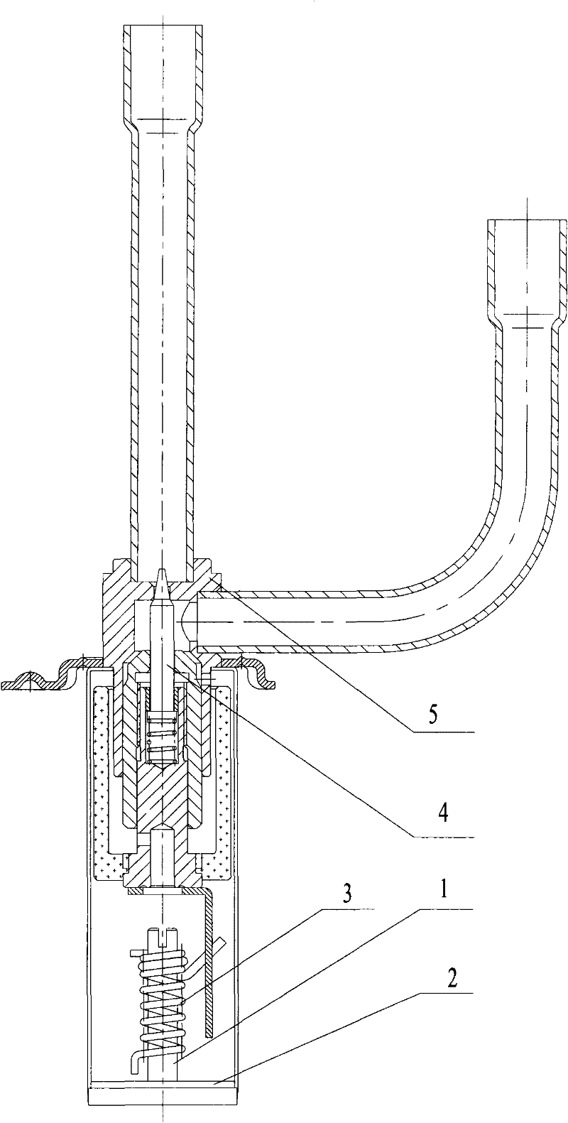
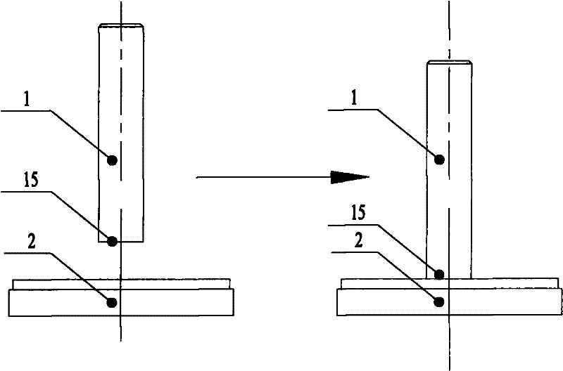
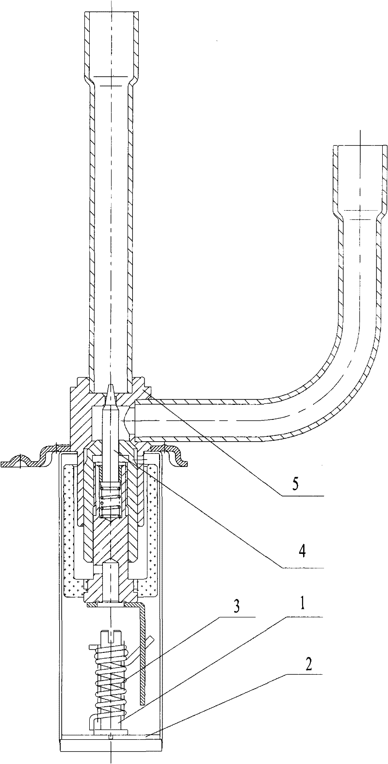
[0038] like Figure 4a as well as Figure 8a , Figure 8b As shown, the welding structure of the small shaft and the cover plate of the electronic expansion valve according to the embodiment of the present invention includes: the small shaft 1 and the cover plate 2 welded together, and the main body of the cover plate 2 is usually a flat plate structure. The welding structure also includes: a positioning structure for enhancing the verticality and welding strength between the small shaft 1 and the cover plate 2 . The positioning structure can be a platform 10 arranged on the welding end 15 of the small shaft 1. During welding, the small shaft 1 is welded on the cover plate 2 through the platform 10; this increases the area of ​​the welding end 15 of the small shaft 1, so it can be Enhance the verticality between the small shaft an...


PUM


Abstract

The invention provides a welding structure of a small shaft and a cover board of an electronic expansion valve, which comprises the small shaft and the cover board which are welded together. The welding structure also comprises a platform arranged on the welding end of the small shaft; the radial cross section of the platform is greater than the radial cross section of the small shaft; and the platform is provided with an upper end surface and a lower end surface, wherein the upper end surface is used for positioning welding equipment, and the lower end surface is used for being welded with the cover board. The invention also provides an electronic expansion valve which comprises the welding structure of the small shaft and the cover board of the electronic expansion valve. The invention is beneficial to self alignment and vertical correction of vertical welding of the small shaft and the cover board, is convenient for clamping and positioning the welding equipment and improves the welding strength, thereby solving the problems of insufficient strength between the small shaft and the cover board, difficult guarantee of verticality and poor product consistency. In addition, a cold heading molding mode is adopted by the small shaft for replacing the traditional lathing mode, thereby the production efficiency of the small shaft is improved and the manufacturing cost is reduced.

Description

technical field [0001] The invention relates to the refrigeration field, and more specifically, to a welding structure of a small shaft and a cover plate of an electronic expansion valve and the electronic expansion valve. Background technique [0002] like figure 1 As shown, the existing electronic expansion valve includes a valve body 5 and a valve core 4 arranged in the valve body, the small shaft 1 and the cover plate 2 are welded together, and the small shaft 1 is sleeved with a spring 3, which can be controlled within a certain limit. The relevant components in the valve body 5 drive the valve core 4 to move up and down in the valve body 5 . like figure 2 As shown, in the existing welding of the small shaft and the cover plate, the bottom end surface (welding end 15) of the small shaft 1 is usually directly welded on the cover plate 2, and the axis of the small shaft 1 is perpendicular to the plane direction of the cover plate 2. Since the small shaft 1 is mainly r...

Claims


Application Information

Patent Timeline
Patent Type & Authority Patents(China)
IPC IPC(8): F16K1/32F16K31/06
Inventor 段宇建沙海建王冠军
Owner ZHEJIANG DUNAN HETIAN METAL CO LTD
Why Eureka
Try Eureka