
Implementation method for debugging information output in embedded system

An embedded system and debugging information technology, which is applied in embedded system debugging and embedded system field, can solve problems such as the impact of normal operation of functional modules, large serial bus bandwidth, large data volume, etc., to achieve stable and reliable working performance, reduce Resource overhead, wide-ranging effects

Active Publication Date: 2010-09-08
SPREADTRUM COMM (SHANGHAI) CO LTD
View PDF0 Cites 11 Cited by
  • Summary
  • Abstract
  • Description
  • Claims
  • Application Information

AI Technical Summary

Problems solved by technology

[0006] (1) The operating object of the debugging information output module of the microsystem is the text to be displayed. If the amount of output information is large, the debugging information output module itself will occupy a lot of system resources (such as CPU time and memory space), which will affect other The normal operation of some functional modules has a certain impact. In extreme cases, other functional modules cannot work normally.
[0007] (2) The data flow of a large amount of debugging information will occupy a large bandwidth of the serial bus, which is not conducive to the transmission of other data on the serial bus between the microsystem and the PC
[0008] The above problems are rooted in the fact that the transmission data is not compressed during the output of the debugging information, so the data volume is relatively large and the efficiency is very low, which brings certain obstacles to the debugging of the embedded system and also affects The operating efficiency of embedded systems has also brought great inconvenience to people's work

Method used


Image

  • Implementation method for debugging information output in embedded system
  • Implementation method for debugging information output in embedded system
  • Implementation method for debugging information output in embedded system

Examples


Embodiment Construction

[0036] In order to understand the technical content of the present invention more clearly, the following examples are given in detail.

[0037] First, the confusing concepts in this manual are explained as follows:

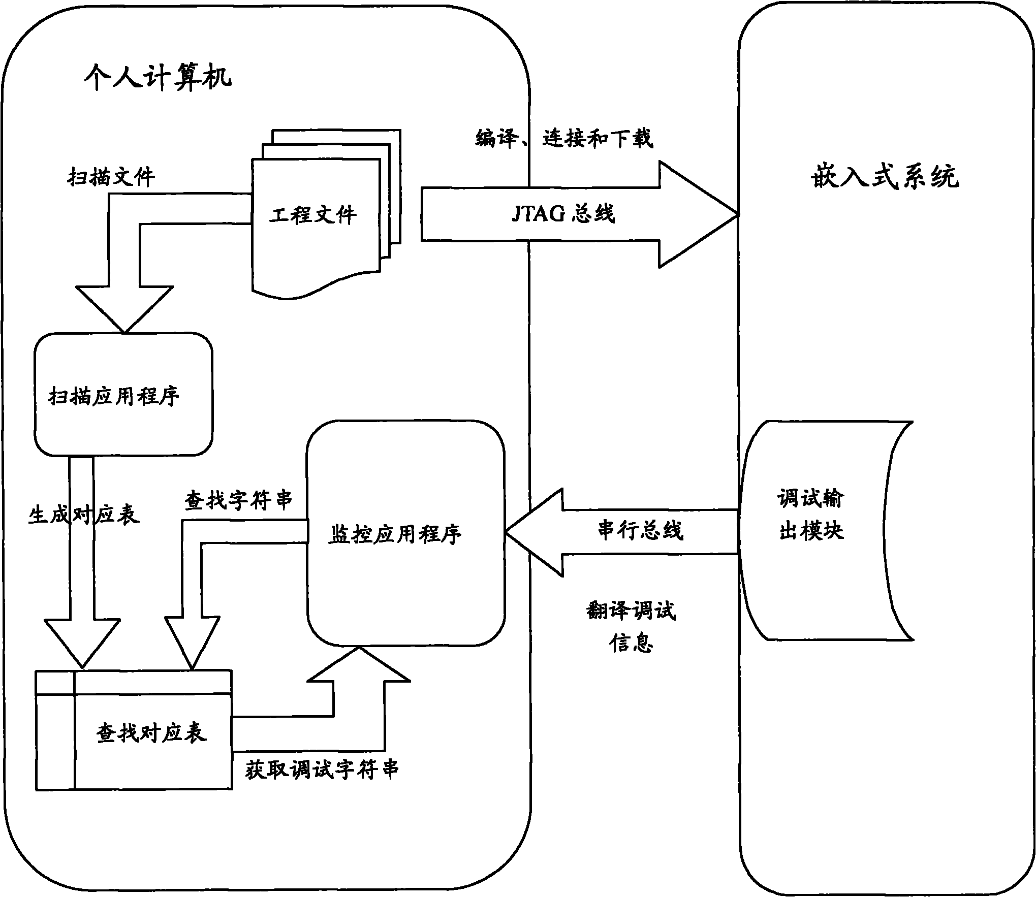
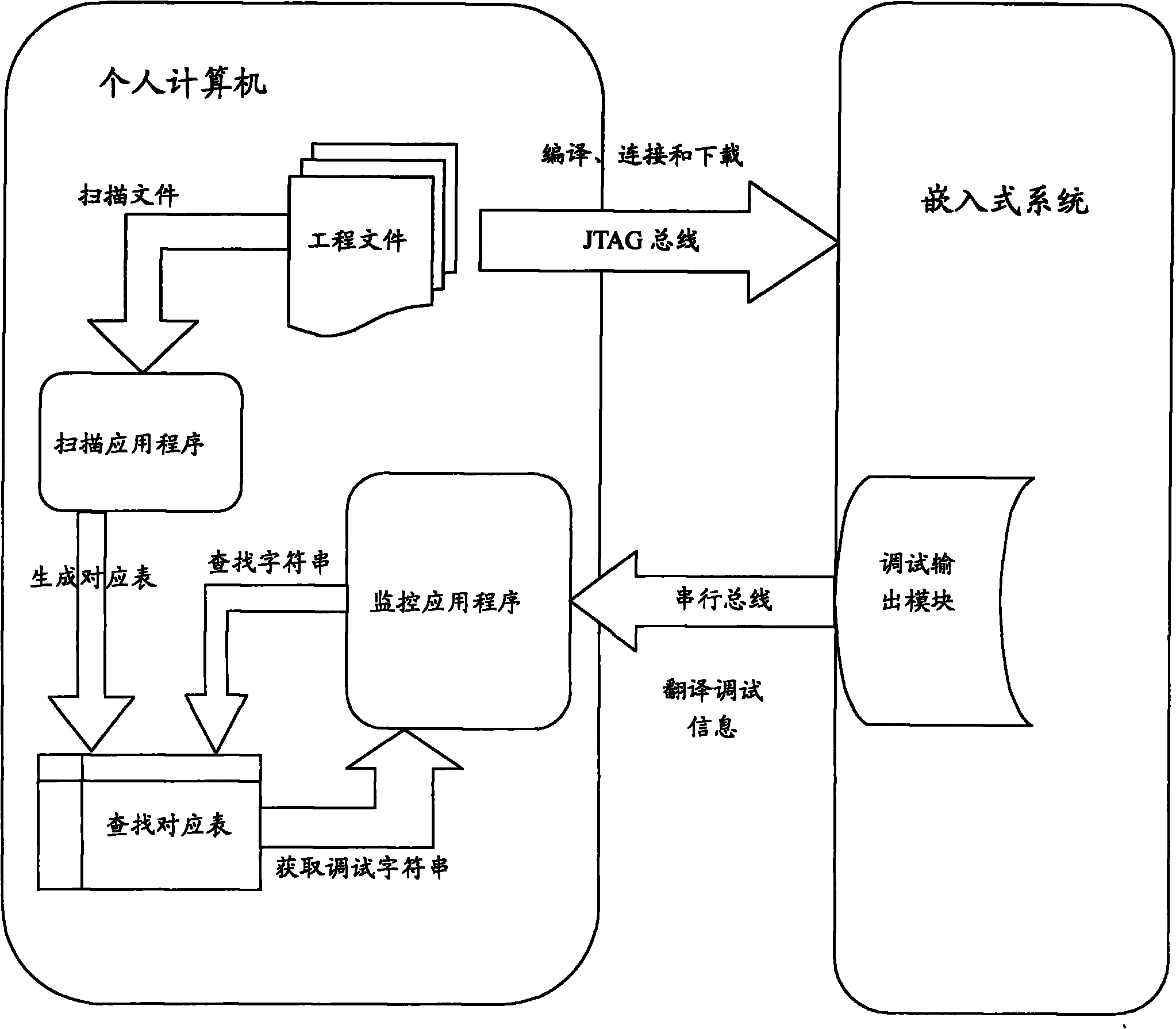
[0038] Scanner: A PC-based application that scans project source code and generates a table. No difference from Scanning Tool.

[0039] Scan project source code: use the scanner to scan the embedded project source code.

[0040] Debug Control Output Device: A PC-based application that accepts debug information from the embedded system and processes it accordingly. No difference from "monitoring tool".

[0041] Debugging output module: a module in the embedded system, which is used to collect, summarize and send debugging information to the PC side.

[0042] Debug location information: information about locating debugging information in the relational table, such as file name and line number.

[0043] Debug information: information that embedded system develop...


PUM


Abstract

The invention relates to an implementation method for debugging information output in an embedded system, comprising the following steps: a screening tool screens an engineering source code to generate the corresponding relation of debugging positioning information and debugging information; when the embedded system operates the engineering source code and needs to output the real-time debugging information, output information with the debugging positioning information is transmitted to debugging control output equipment; the debugging control output equipment obtains the debugging positioning information and finds the debugging information according to the corresponding relation of the debugging positioning information and the debugging information; and the debugging control output equipment displays the debugging information. The implementation method for debugging information input in the embedded system greatly reduces the system expenditure of a debugging output module of the embedded system and saves bandwidth occupied by the debugging information data on a universal serial bus to bring convenience for the transmission of other data. The method has simple and convenient process, stable and reliable working performance and wide applicable range, thus bringing great convenience for debugging the embedded system.

Description

technical field [0001] The invention relates to the field of embedded systems, in particular to the technical field of debugging of embedded systems, in particular to a method for realizing debugging information output in an embedded system. Background technique [0002] Debugging and testing of embedded system (microsystem) is a very important part of embedded system design. Efficiently obtaining various information when the embedded system is running is the basis of debugging and testing, and it is also the place that should be paid attention to at the beginning of system design. A good debugging information output method can effectively reduce the proportion of the debugging information output module in the resource consumption of the entire microsystem, and give other functional modules more space to play. [0003] The so-called debug information (signpost) of the embedded system refers to the output and print information through function calls in the source code of the...

Claims


Application Information

Patent Timeline
Patent Type & Authority Applications(China)
IPC IPC(8): G06F11/36
Inventor 赖运东阎书印吴佰年
Owner SPREADTRUM COMM (SHANGHAI) CO LTD
Learn More