Joining structure of sheet-metal components and image forming device

A sheet metal part, combined structure technology, applied in the field of image forming devices, can solve the problems of increased cost and high processing difficulty, and achieve the effect of ensuring grounding performance and solving EMI problems

Active Publication Date: 2010-09-08
KONICA MINOLTA BUSINESS TECH INC
View PDF2 Cites 0 Cited by
  • Summary
  • Abstract
  • Description
  • Claims
  • Application Information

AI Technical Summary

Problems solved by technology

However, such countermeasures require the use of special tools to form protrusions on the sheet metal parts, and the processing is difficult, resulting in an increase in cost.

Method used


Image

  • Joining structure of sheet-metal components and image forming device
  • Joining structure of sheet-metal components and image forming device
  • Joining structure of sheet-metal components and image forming device

Examples


no. 1 example

[0030] (for the first embodiment, refer to Figure 2 ~ Figure 4 )

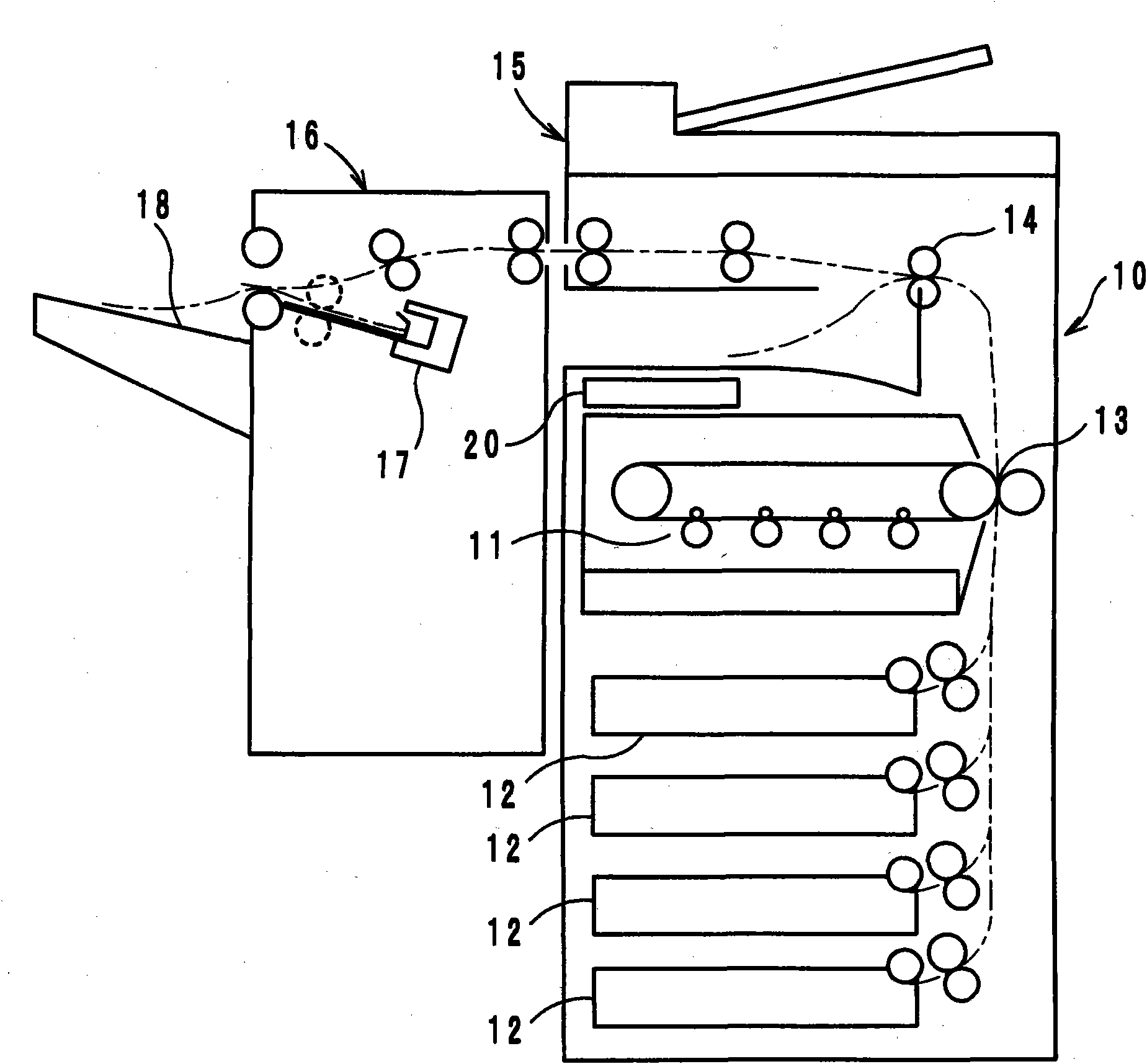
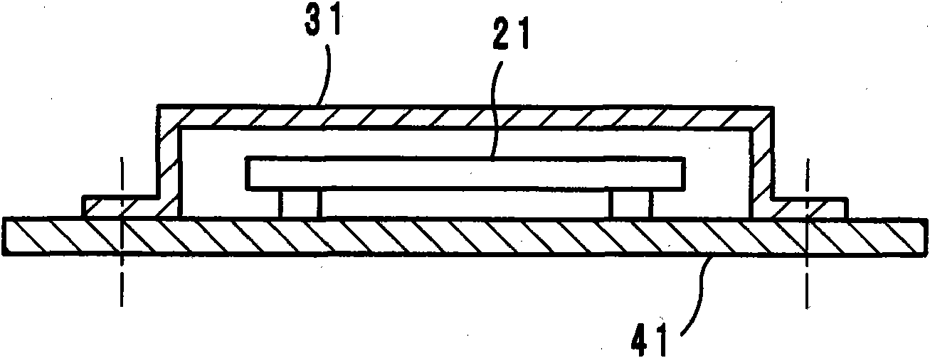
[0031] In the control unit 20, each paper feeding cassette 12, and the finisher 16, etc., a control board is arranged, such as figure 2 As shown, such a control board 21 is mounted on a structural sheet metal part 41 (hereinafter referred to as a second sheet metal part) as a base, and is covered by a shield cover 31 (hereinafter referred to as a first sheet metal part). The joining structure of the sheet metal parts according to the present invention, in the first embodiment, is a structure for joining the first sheet metal part 31 to the second sheet metal part 41 and ensuring an electrically conductive state.

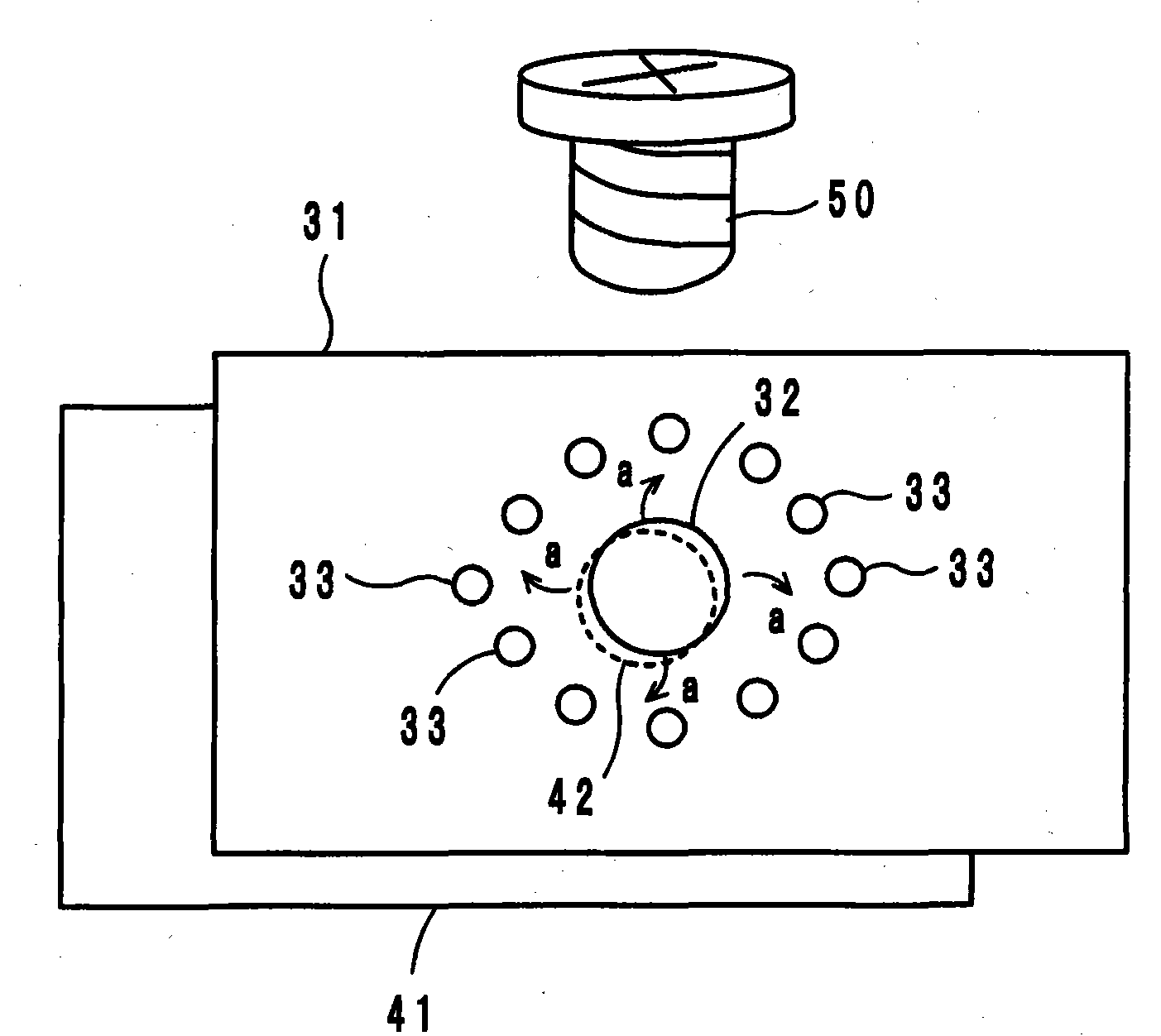
[0032] Specifically, as image 3 As shown, a first pre-hole 32 with a diameter smaller than that of the screw part 50 is formed on the first sheet metal part 31, and a plurality of first pre-holes 32 with a diameter smaller than the first pre-hole 32 are formed around the first pre-hole 32. Small...

no. 2 example

[0036] (Second embodiment, refer to Figure 5 and Figure 6 )

[0037] The combination structure of the second embodiment, such as Figure 5As shown, a second pre-hole 42 having a diameter smaller than that of the screw part 50 is also formed on the second sheet metal part 41 , and a second small hole 43 is formed at a position opposite to the above-mentioned first small hole 33 . The bonding process carried out by the screw part 50 is as Figure 4 As shown, in this second embodiment, since the punching mark of the second small hole 43 is not coated with an insulating resin film, the first and second sheet metal parts 31, 41 are combined. The electrical conduction between the two in the state becomes better.

[0038] In addition, the diameter of the second pre-hole 42 formed on the second sheet metal part 41 is also formed to be smaller than the screw part 50, so when the screw part 50 is used for fastening, the second pre-hole 42 is also formed. deformation force. Under...

no. 3 example

[0041] (for the third embodiment, refer to Figure 9 )

[0042] The combined structure of the third embodiment, such as Figure 9 As shown, knurling is applied to the area 44 facing the first small hole 33 on the bonding surface of the second sheet metal part 41 . Knurling processing is a known processing method in which a knurling tool is mounted on a lathe or the like and rotated to form a desired notch on the surface of an object.

[0043] In the third embodiment, the first small hole 33 is crushed to form a protrusion that is in frictional contact with the knurl forming area 44, so that the first and second sheet metal parts 31, 41 are combined in a good conduction state. .

[0044] (other embodiments)


PUM


Abstract

In the combination structure of sheet metal parts in which a first sheet metal part 31 and a second sheet metal part 41 are combined by a screw member 50 with the respective connecting surfaces being opposed to each other, a first prepared hole 32 smaller in diameter than the screw member 50 is formed in the first sheet metal part 31, and a number of first small holes 33 smaller in diameter than the first prepared hole 32 are formed around the first prepared hole 32. When the first part 31 is connected to the second part 41 by the screw member 50, a strain force is generated around the first prepared hole 32 by screwing the screw member 50 to the first hole 32, and projections formed in the first small holes 33 are brought into contact with the second part 41 by the strain force.

Description

technical field [0001] The present invention relates to a joining structure of sheet metal parts, in particular to a joining structure of sheet metal parts in which two sheet metal parts are joined together with screw parts in such a manner that their joining faces face each other, and a copier, printer, etc. having the joining structure image forming device. Background technique [0002] Conventionally, in image forming apparatuses such as copiers, printers, and facsimiles, electronic equipment such as computers and communication equipment, and various electrical equipment, various parts and units have been assembled on metal structures forming their frames, and A structure in which an exterior body is assembled on the outer surface. [0003] At present, metal structures, using joint parts such as screws or rivets, or welding, etc., combine multiple sheet metal parts in such a way that their joint faces face each other, and are also used as grounding means to solve electro...

Claims


Application Information

Patent Timeline
Patent Type & Authority Applications(China)
IPC IPC(8): G03G15/00F16B5/02H05K9/00
CPCG03G2221/1678G03G21/1642
Inventor 林健一渡边功安藤寿邦辻原清人
Owner KONICA MINOLTA BUSINESS TECH INC
Why Eureka
Try Eureka