Production line and process for punching U-shaped beam

A production line and U-shaped technology, which is applied in the field of U-shaped beam punching, can solve the problems of high cost and complex structure of the production line, and achieve the effects of reducing production costs, convenient operation, and simplifying subsequent processes

Inactive Publication Date: 2010-09-15
SHANDONG TUOWEI CNC EQUIP
View PDF4 Cites 13 Cited by
  • Summary
  • Abstract
  • Description
  • Claims
  • Application Information

AI Technical Summary

Problems solved by technology

However, the airfoil punch needs to be repositioned and processed, and two airfoil hosts are required on the left and right. The entire production line has a complex structure and high cost

Method used


Image

  • Production line and process for punching U-shaped beam
  • Production line and process for punching U-shaped beam
  • Production line and process for punching U-shaped beam

Examples


Embodiment 1

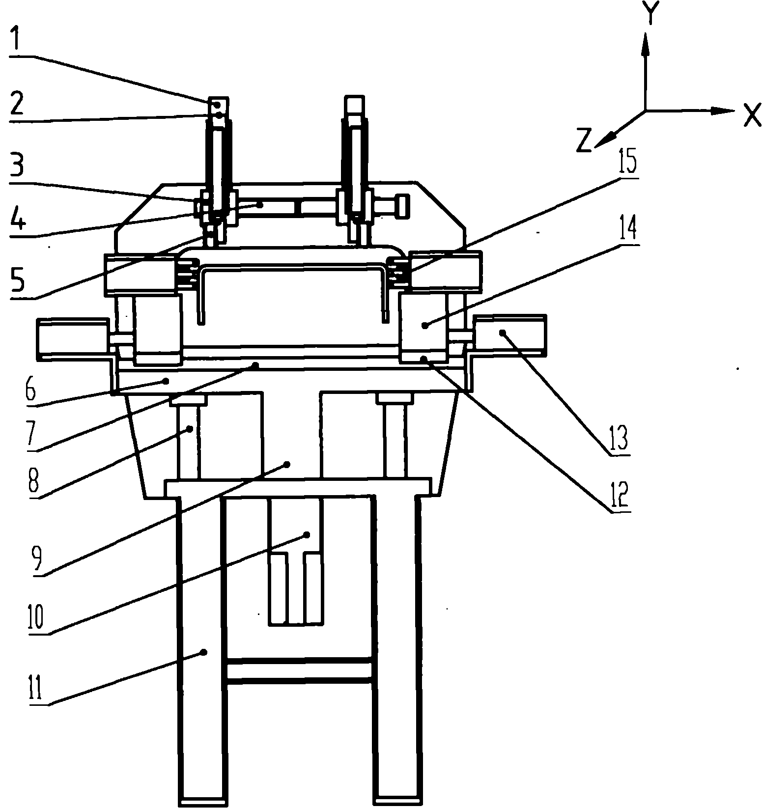
[0033] Reference attached figure 2 , an airfoil sample punching machine D, the airfoil sample punching machine D includes a frame 11, two sets of detection devices, two sets of adjustment structures, two sets of sample impulse power heads and a lifting device, wherein the detection device is used It is used to detect the height deviation of the left and right airfoils of the U-shaped beam; the adjustment structure is installed at the lower part of the detection device to adjust the distance between the two sets of detection devices and the left and right airfoils; two sets of sample impulse heads are respectively used for the U-shaped beam The marking on the left and right airfoils is located under the detection device; the lifting device is used to adjust the height of the power head of the sample punch relative to the airfoil according to the detected height deviation of the left and right airfoils, and is located under the power head of the sample punch.

[0034] The detec...

Embodiment 2

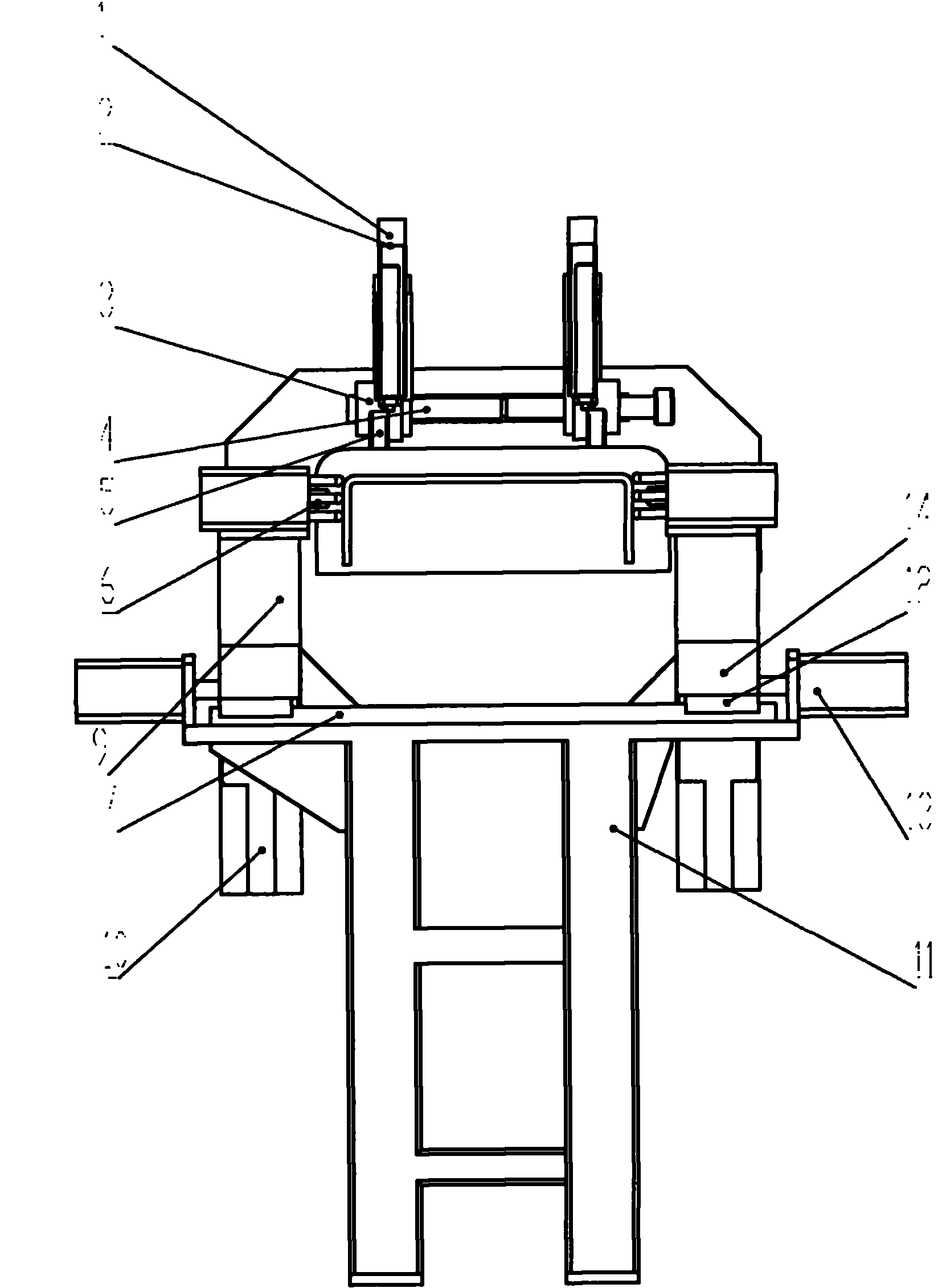
[0042] Such as image 3 The lifting device of the airfoil sample punching machine D shown includes two lifting structures 9 respectively connected to the punch cylinder 6 and two servo motors 10 for controlling the movement of the lifting structure 9 in the Y direction. Other parts of the structure embodiment 1 .

[0043] The working principle of the lifting device: when the detection device measures the deviation value and compensates the deviation value to the coordinate value in the Z direction, the left and right sample punches control the movement of the lifting structure 9 through their respective servo motors 10 to drive the sample punching power head to feed, and then use the punch The head cylinder is used as the power to drive the left and right sample punches to mark with sample punches at the positions of the left and right wing faces.

[0044] In Embodiment 1, a servo motor 10 drives the left and right sample impulse heads 15. When the heights of the left and rig...


PUM


Abstract

The invention discloses a production line and a process for punching a U-shaped beam. The production line for punching a U-shaped beam comprises a feeding mechanism, a workpiece feeding device, a punching main machine for punching the ventral side of the U-shaped beam, a blanking feeding device and a blanking device, wherein a wing-surface punching machine for punching and marking the wing surfaces of the U-shaped beam is arranged at one side of the punching main machine. The process for punching a U-shaped beam comprises the following steps of: (1) placing the U-shaped beam on the workpiece feeding device; (2) conveying the U-shaped beam in the punching main machine and punching the ventral side; (3) enabling the U-shaped beam to enter the wing-surface punching machine from the punching main machine and marking at corresponding positions of the wing surfaces of the U-shaped beam; and (4) conveying the U-shaped beam to the next working procedure by the blanking device. The invention has the advantages that the subsequent working procedures are simplified, the production efficiency is improved, and the production cost is decreased because the hole positions of the left wing surface and the right wing surface of the U-shaped beam are punched and marked before or after the ventral side is punched so as to avoid repositioning hole positions in the next working procedure.

Description

technical field [0001] The invention relates to a production line and process for punching U-shaped beams, which are used for punching processing of frame longitudinal beams in the automobile industry and belong to the field of U-shaped beam punching. Background technique [0002] In the existing automobile industry, the punching of the U-shaped longitudinal beam of the vehicle frame generally adopts a numerically controlled flat punching production line. The production equipment used for punching U-shaped longitudinal beams includes three-sided punching, belly punching and wing punching. [0003] Three-sided punching equipment generally requires five punching machines, namely: the first small ventral punching machine, the large ventral punching machine, the second small ventral punching machine, and the left and right wing punching machines. This production process has low production efficiency, low operation reliability and high cost due to many equipments, complex struct...

Claims


Application Information

Patent Timeline
Patent Type & Authority Applications(China)
IPC IPC(8): B21D28/32
Inventor 栾红霞崔洪刚
Owner SHANDONG TUOWEI CNC EQUIP
Why Eureka
Try Eureka