Novel multifunctional speed reducer

A multi-functional, speed reducer technology, applied in door/window fittings, buildings, wing fan control mechanisms, etc., which can solve the problems of scattered and complex mechanisms, inflexible and inaccurate stroke control, etc.

Inactive Publication Date: 2010-09-15
孙淑勤
View PDF0 Cites 2 Cited by
  • Summary
  • Abstract
  • Description
  • Claims
  • Application Information

AI Technical Summary

Problems solved by technology

[0003] The purpose of the present invention is to provide a multi-functional reducer mainly used for integrated transmission, deceleration, stroke control, and power clutch of electric doors, which overcomes the limitations of the existing power mechanism, deceleration mechanism, and stroke control

Method used


Image

  • Novel multifunctional speed reducer
  • Novel multifunctional speed reducer
  • Novel multifunctional speed reducer

Examples


Embodiment Construction

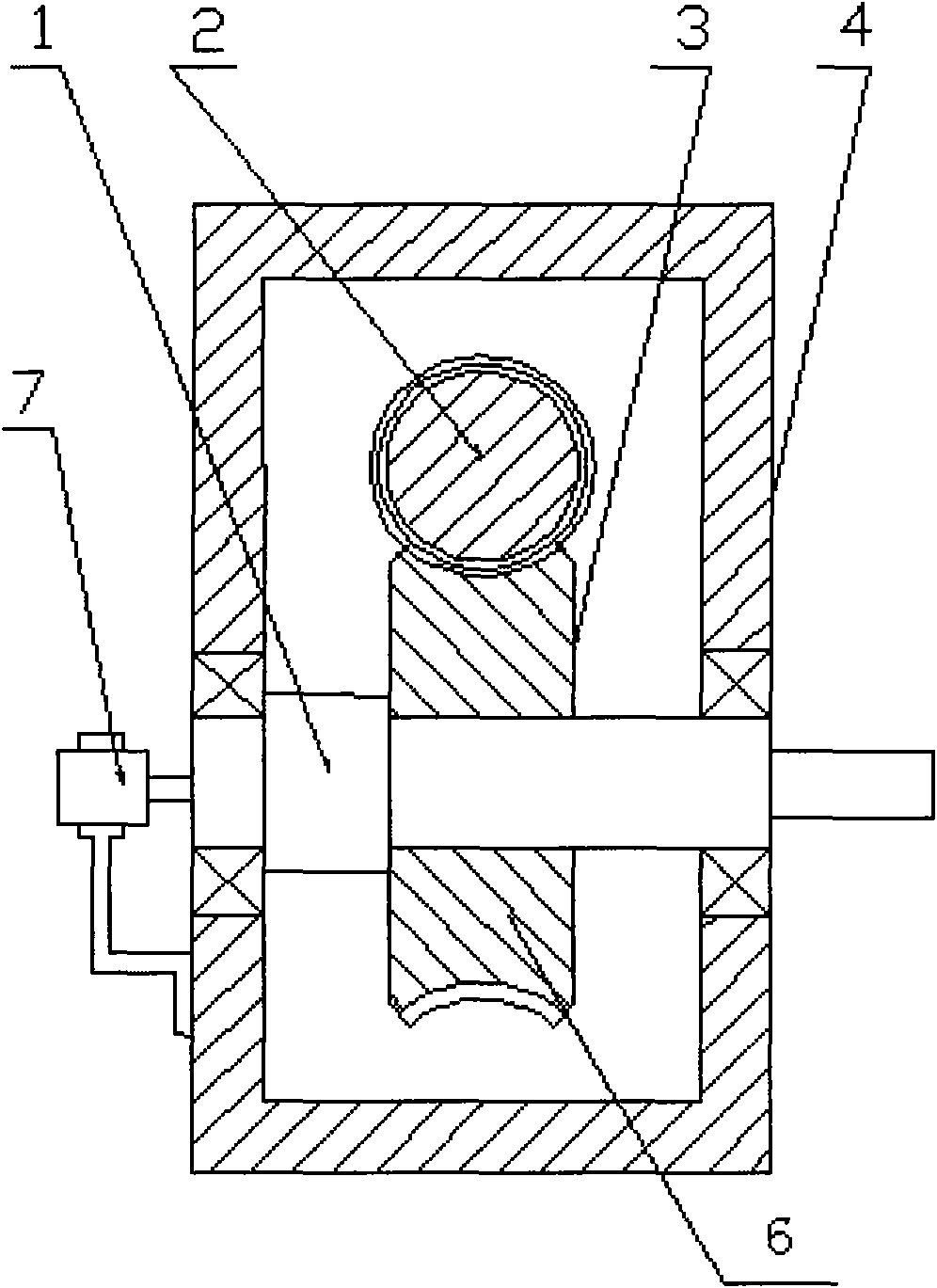
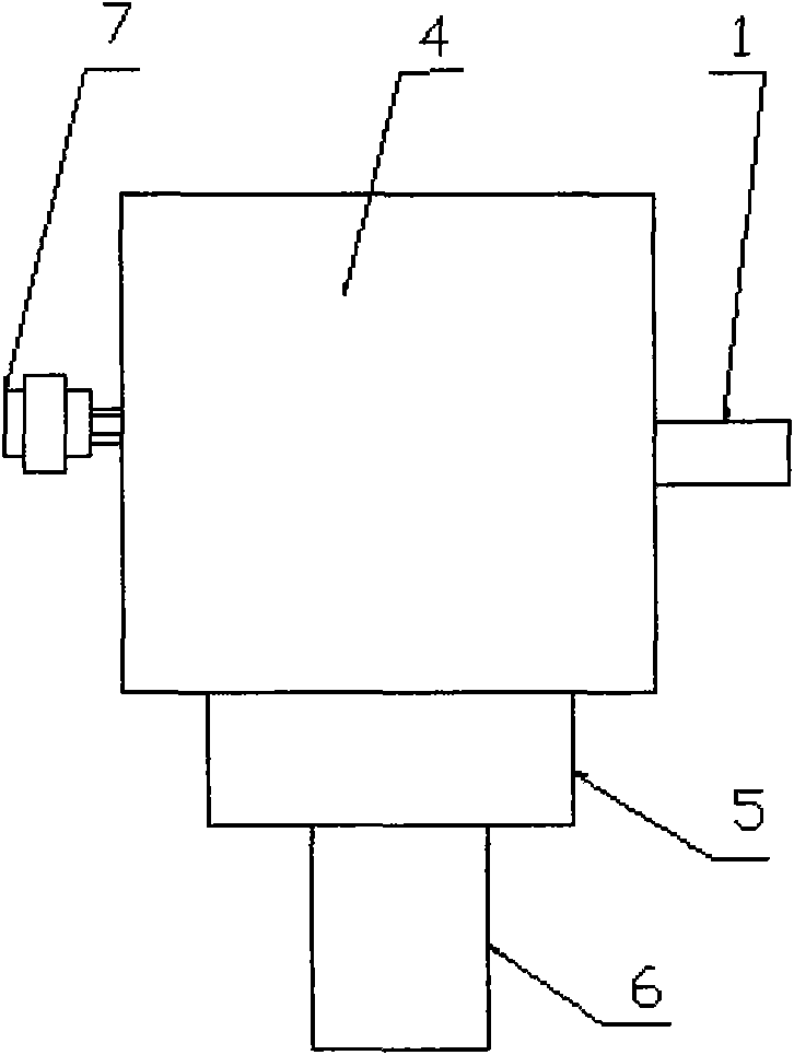
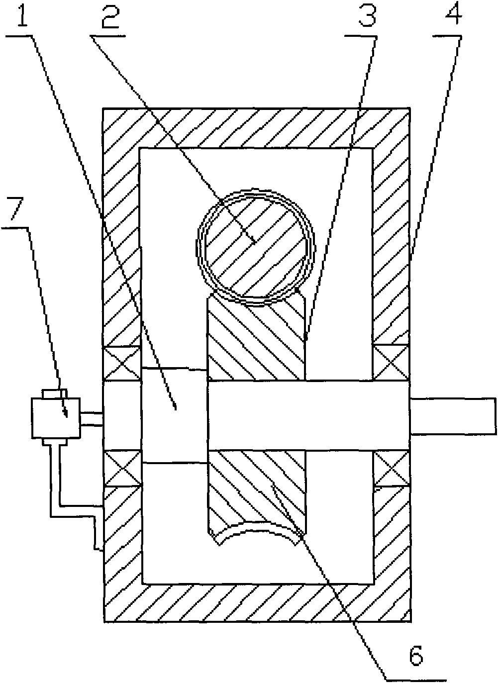
[0009] Install and fix the turbine (3), the worm (2), and the output shaft (1) in the correct way inside the box (4), connect one end of the electromagnetic clutch (5) to one end of the worm (2), At the same time, install and fix the electromagnetic clutch (5) on the box body (4) with an appropriate method, connect the output shaft of the motor (6) with the corresponding part of the electromagnetic clutch (5), and connect it with an appropriate method. It is installed and fixed so that it becomes the same fixed whole with the casing (4) and the electromagnetic clutch (5). Then connect the rotary encoder (7) to the output shaft (1) and fix it on the box body (4) to form a whole. In the above mechanism, the rotary encoder (7) converts the corresponding rotation amount into the corresponding stroke distance to realize The control of the motor (6) and the electromagnetic clutch (5), thereby realizing the corresponding control of the electric door.


PUM


Abstract

The invention relates to a novel multifunctional speed reducer. A turbine, a worm rod and an output shaft are arranged and fixed in a tank body by a property method. One end of an electromagnetic clutch is connected with one end of the worm rod. Simultaneously, the electromagnetic clutch is arranged and fixed on the tank body by a proper method. An output shaft of a motor is connected with the corresponding part of the electromagnetic clutch and is arranged and fixed by a proper method so that the output shaft, the tank body and the electromagnetic clutch form an fixed whole. A rotary encoder is connected with the output shaft and fixed on the tank body to form a whole. In the mechanism, the corresponding rotation amount is converted into the corresponding travel distance by the rotary encoder so as to control the motor and the electromagnetic clutch, thereby correspondingly controlling the electrical door.

Description

technical field [0001] The invention relates to a speed reducer, in particular to a novel multifunctional speed reducer. It belongs to the technical field of electromechanical equipment. Background technique [0002] At present, the reducers used for electric doors are all general-purpose reducers. They are integrated with the matching motor, transmission device and corresponding travel switch to realize the control of the electric door. Therefore, the current transmission of the electric door , control, and other corresponding devices have scattered and complicated mechanisms, especially because the scattered structures cause the corresponding parts to be exposed, so they are easy to damage and malfunction. In addition, because the stroke control is not linked with the power clutch, the stroke control is not flexible and accurate. Contents of the invention [0003] The purpose of the present invention is to provide a multi-functional reducer mainly used for integrated t...

Claims


Application Information

Patent Timeline
IPC IPC(8): E05F15/10E05F15/603
Inventor 孙淑勤
Owner 孙淑勤
Why Eureka
Try Eureka