
Optical fiber clamp

An optical fiber and fixture technology, which is applied in the field of optical fiber fixtures with low stress and low micro-bending loss, can solve the problems of inconvenient operation and large volume of the optical fiber fixture, and achieve the effects of uniform cross-sectional distribution, small stress, and small micro-bending loss.

Inactive Publication Date: 2011-09-14
ZHEJIANG UNIV
View PDF0 Cites 0 Cited by
  • Summary
  • Abstract
  • Description
  • Claims
  • Application Information

AI Technical Summary

Problems solved by technology

Moreover, the existing optical fiber clamp has a large volume and is inconvenient to operate. It takes two stages of placing the optical fiber and clamping the optical fiber, and the two-handed operation can complete the clamping of the optical fiber.

Method used


Image

  • Optical fiber clamp
  • Optical fiber clamp
  • Optical fiber clamp

Examples


Embodiment Construction

[0009] The present invention will be further described below in conjunction with the accompanying drawings and specific embodiments.

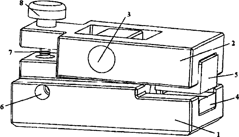
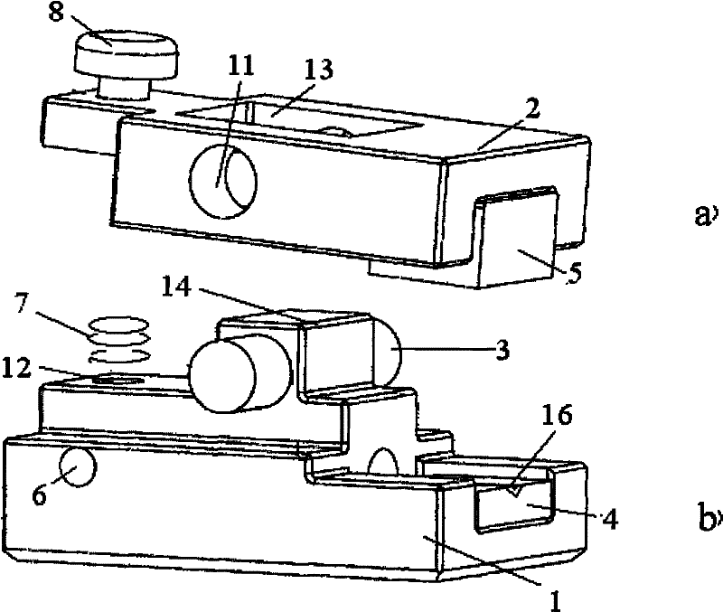
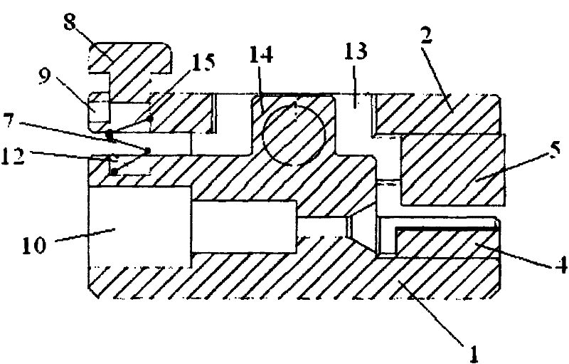
[0010] Referring to the accompanying drawings, the optical fiber clamp of the present invention includes: a base 1 and a top cover 2, the base 1 has a square convex body 14, the top cover 2 has a square through hole 13 for the square convex body 14 on the base to be inserted, the square convex body The body 14 is equipped with a horizontal bar 3, and the two ends of the horizontal bar 3 extend into the through holes 11 on both sides of the square through hole 13. The base and the top cover are swingable with the horizontal bar 3 as a lever support, and the rear end of the base 1 has an opening. Upward groove, there is a first rubber gasket 4 in the groove, the rear end of the top cover 2 has a downward groove, there is a second rubber gasket 5 in the groove, and there is a fiber optic FC head on the base 1. The stepped axial hole 10 is inserted...


PUM


Abstract

The invention discloses an optical fiber clamp comprising a base and a top cover, wherein a square convex body is arranged on the base, a square through hole for embedding the square convex body on the base is arranged on the top cover, a horizontal rod is assembled on the square convex body, both ends of the horizontal rod extend into through holes at both sides of the square through hole, the base and the top cover can swing by using the horizontal rod as lever support, the back ends of the base and the top cover are respectively provided with a rubber gasket, a staircase-shaped axial hole used for an optical fiber FC head to extend in and be communicated with a groove at the back end of the base is arranged on the base, and the front end of the top cover is provided with a spring for adjusting the stress size of an optical fiber. The optical fiber clamp fixes the optical fiber by utilizing the elastic force of the spring and the lever principle, has small size and convenient operation, can avoid the hard contact of the optical fiber and the staircase-shaped axial hole by utilizing the rubber gasket, the elastic force on the optical fiber is not as hard as the hard force of a magnetic body so that the optical fiber receives small stress, and the optical fiber clamp has uniform section distribution, less micro-bending loss and adjustable length of the spring in the clamp and can ensure the controllability of optical fiber loss.

Description

technical field [0001] The invention relates to an optical fiber clamp, in particular to an optical fiber clamp with low stress and low microbend loss. Background technique [0002] Optical fiber plays an irreplaceable role in optical sensing and optical fiber communication. As a device for fixing optical fibers, optical fiber clamps have become particularly important. However, in many applications, traditional optical fiber clamps use electromagnet attraction to fix optical fibers. Due to The attractive impulse of the magnet is large, resulting in a large stress on the side of the fiber and even sometimes breaking the fiber. Stress on the fiber section will cause stress birefringence, microbend loss, elastic-optic effect and other factors. In optical sensing, slight changes in the polarization state when light propagates in the optical fiber will cause inaccurate sensing accuracy. Microbend loss also needs to be avoided as far as possible in the field of optical fiber comm...

Claims


Application Information

Patent Timeline
Patent Type & Authority Patents(China)
IPC IPC(8): G02B6/36
Inventor 张彩妮孙丽艳舒晓武刘承
Owner ZHEJIANG UNIV
Learn More