
Device and method for adjusting view field of spliced panoramic camera

A panorama camera and adjustment device technology, which is applied to the parts of color TV, parts of TV system, TV, etc., can solve the problem of inability to adjust the field of view of the camera, so as to reduce the number of motion control devices, reduce the cost, and reduce the field of view. wide range of effects

Active Publication Date: 2010-09-15
HUNAN VISION SPLEND PHOTOELECTRIC TECH
View PDF3 Cites 48 Cited by
  • Summary
  • Abstract
  • Description
  • Claims
  • Application Information

AI Technical Summary

Problems solved by technology

[0005] Aiming at the problem that the commonly used splicing panoramic cameras in the prior art cannot adjust the camera field of view because each camera is installed on a slope with a fixed inclination angle, the present invention aims to propose a device and method for adjusting the field of view of the splicing panoramic cameras, which can ensure the splicing Under the premise of the panoramic effect, the adjustment of the field of view of the stitching panoramic camera can be realized by simply, effectively and quickly adjusting the pitch angle of each camera synchronously, so as to meet the objective needs of adjusting the field of view of the camera in the practical application of the stitching panoramic camera

Method used


Image

  • Device and method for adjusting view field of spliced panoramic camera
  • Device and method for adjusting view field of spliced panoramic camera
  • Device and method for adjusting view field of spliced panoramic camera

Examples


Embodiment Construction

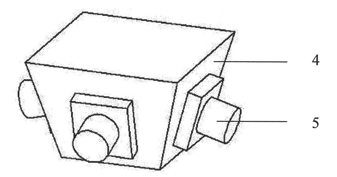
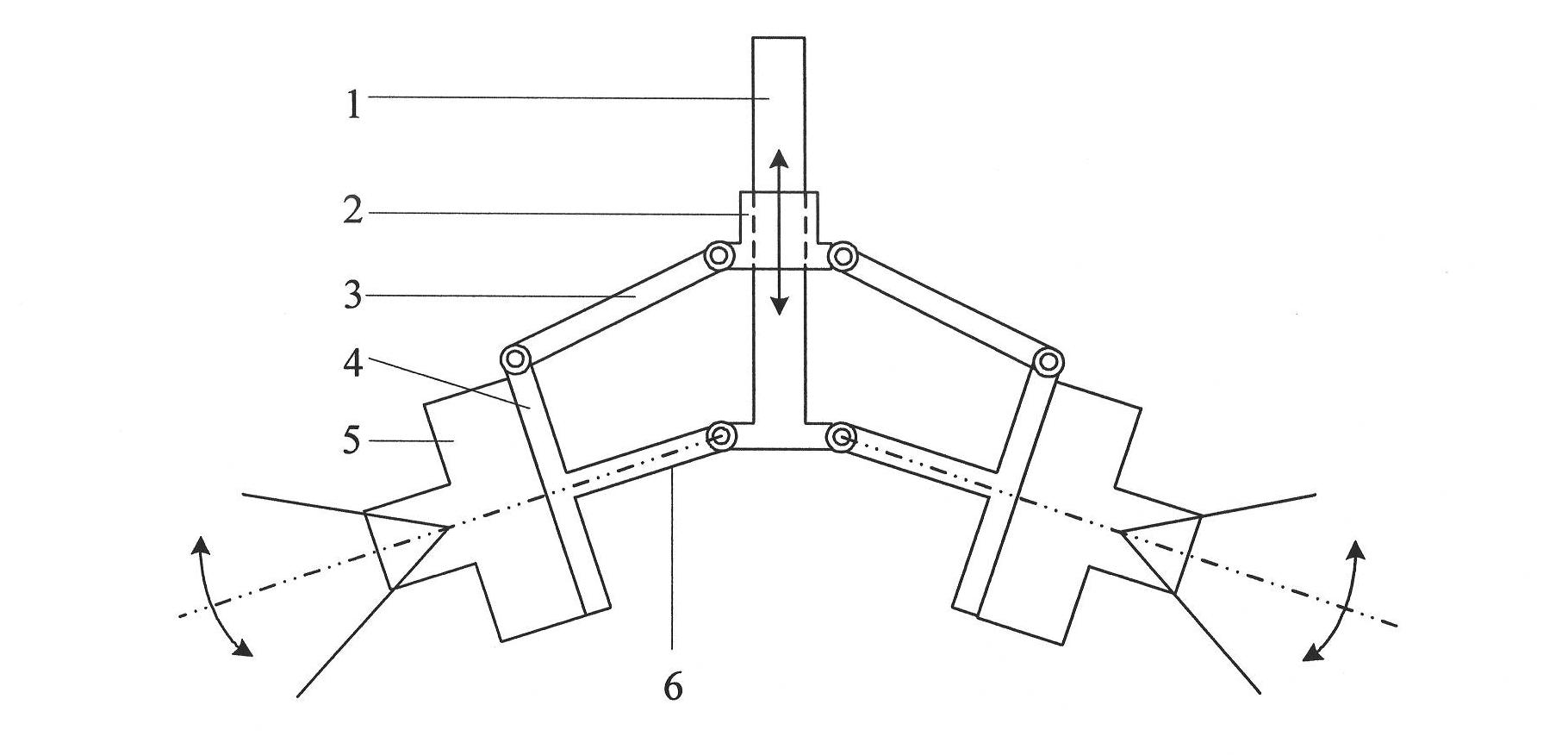
[0055] This embodiment provides an adjustment device for splicing the field of view of a panoramic camera, such as figure 2 , 3 As shown, it includes a spliced ​​panoramic camera field of view adjustment device housing composed of a camera housing 10 and a transparent cover 9. The inside of the housing is provided with a slope 4 for installing a camera 5 and a guide rod 1 vertically installed on a pallet 8 placed horizontally. The inner side of the camera housing 10 is fixed with a horizontal fixed plate 11, and the bottom of the fixed plate 11 is vertically mounted with a guide rod 1 and a stepping motor 12. The guide rod 1 is provided with a sleeve 2 that slides linearly along the guide rod, and the slope 4 is hinged with the sleeve 2 through the upper connecting rod 3 hinged to its upper edge. The lower connecting rod 6, the inclined plane is hinged with the lower end of the guide rod 1 through the lower connecting rod 6. Wherein the adjustment rods of each camera, that ...


PUM


Abstract

The invention discloses a device and a method for adjusting the view field of a spliced panoramic camera. The adjusting device comprises an inclined plane, a guide rod and an adjusting lever, wherein a camera is arranged on the inclined plane; the adjusting lever consists of an upper connecting rod and a lower connecting rod; the guide rod is provided with a sleeve sliding linearly along the guide rod; the inclined plane is hinged with the sleeve through the upper connecting rod which is hinged with the upper edge of the inclined plane; the inner side of the inclined plane is vertically fixed with the lower connecting rod which is coaxial with the optical axis of the camera; and the inclined plane is hinged with the lower end of the guide rod through the lower connecting rod. The adjusting method comprises the following steps of: calculating a required inclination angle alpha 1 and a current inclination angle alpha 0 of the optical axis of the camera according to the view field adjusting range of the camera; synchronously adjusting the inclination angle of each camera optical axis of the spliced panoramic camera to the alpha 1; and regenerating a spliced panoramic image according to the adjusted inclination angle alpha 1 of the camera optical axis to complete view field adjustment. The device and the method are simple and effective and meet the objective requirement on the adjustment of the view field of the camera in practical application of the spliced panoramic camera.

Description

Technical field: [0001] The invention relates to the field of splicing panoramic imaging, in particular to a simple and effective adjustment device and method for splicing panoramic camera viewing fields that can meet the requirements of different viewing fields under the premise of ensuring no gaps and no dislocations in the splicing panoramic view. Background technique: [0002] Stitching panoramic imaging technology uses a fixed viewpoint to shoot multiple overlapping images in various directions, and then seamlessly stitches them according to the information of the overlapping parts of the boundaries (or camera position information) to obtain a panoramic image. Compared with catadioptric panoramic imaging technology, mosaic panoramic imaging technology has the advantages of high resolution and uniform imaging, and can be widely used in large field of view and large-scale omnidirectional video surveillance (airports, squares, etc.). [0003] Commonly used stitching panora...

Claims


Application Information

Patent Timeline
Patent Type & Authority Applications(China)
IPC IPC(8): G03B37/04G02B7/02H04N5/232
Inventor 张茂军王炜王斌徐玮熊志辉
Owner HUNAN VISION SPLEND PHOTOELECTRIC TECH
Learn More