Al technical title is built by PatSnap Al team. It summarizes the technical point description of the patent document.
A technology of relays and moving reeds, applied in the field of electronic control devices, can solve the problems of affecting the service life of coils, wasting electric energy, and increasing the heat generated by coils
Inactive Publication Date: 2010-09-15
NINGBO TIANBO GANGLIAN ELECTRONICS
View PDF6 Cites 1 Cited by
Summary
Abstract
Description
Claims
Application Information
AI Technical Summary
This helps you quickly interpret patents by identifying the three key elements:
Problems solved by technology
Method used
Benefits of technology
Problems solved by technology
[0002] We know that when the relay in the conventional technology is working, as long as a certain voltage is applied to both ends of the coil, a certain current will flow through the coil, thereby generating an electromagnetic effect, and the armature will drive the reed to move under the action of electromagnetic force. The moving contact of the moving contact and the static contact (normally open contact) on the static reed are sucked together. After the moving contact and the static contact are pulled together, the external circuit is connected. In order to keep the external circuit in a conducting state, we need Continue to supply power to the coil to keep the moving contact and the static contact closed. However, supplying power to the coil for a long time will not only cause a waste of electric energy, but also cause the heat generation of the coil to continue to increase, which will affect the service life of the coil.
Method used
Image
Click on the blue label to locate the original text in one second.
Reading with bidirectional positioning of images and text.
Examples
Embodiment Construction
[0013] The relay of the present invention will be further described below in conjunction with the accompanying drawings and specific embodiments:
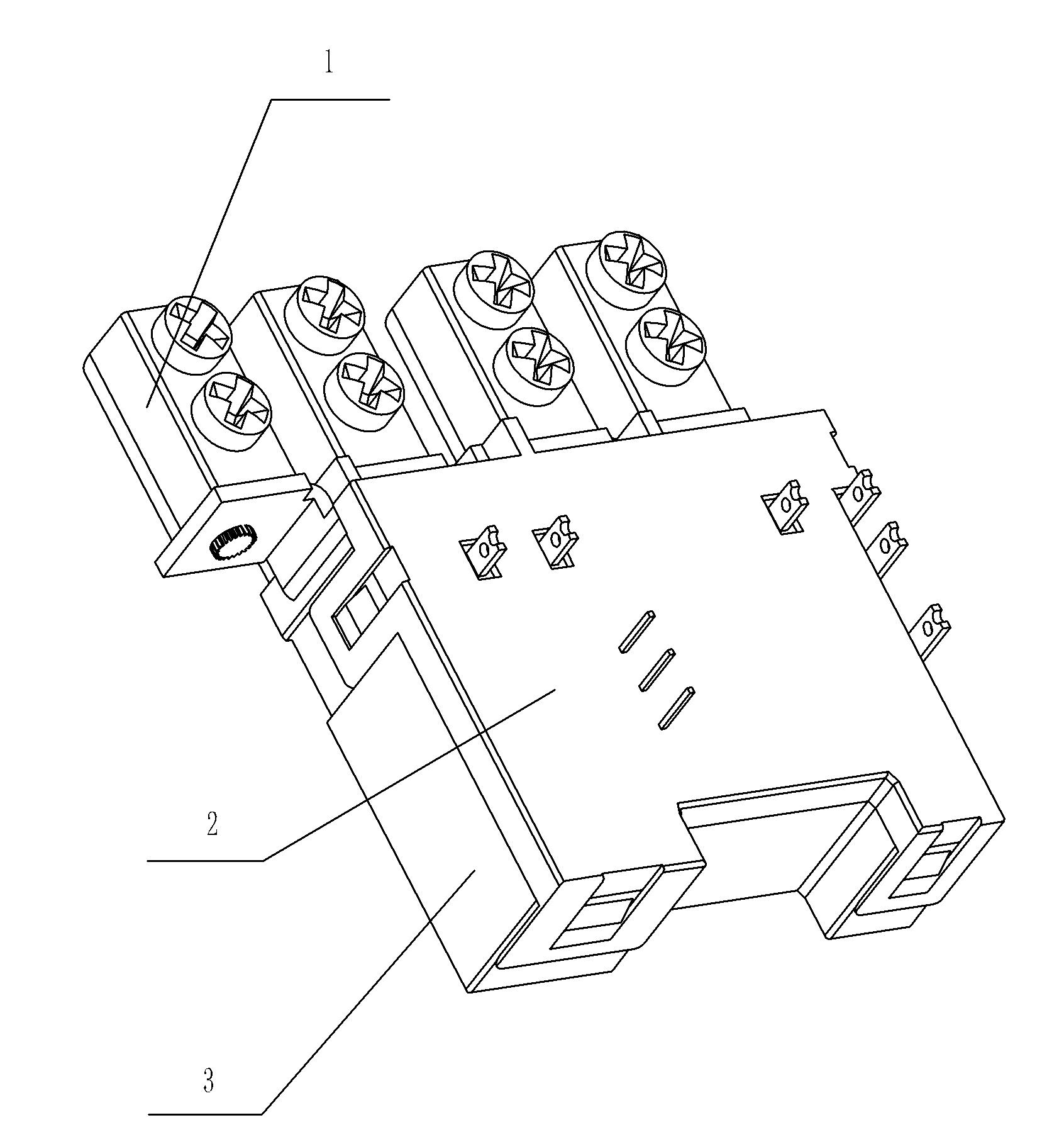
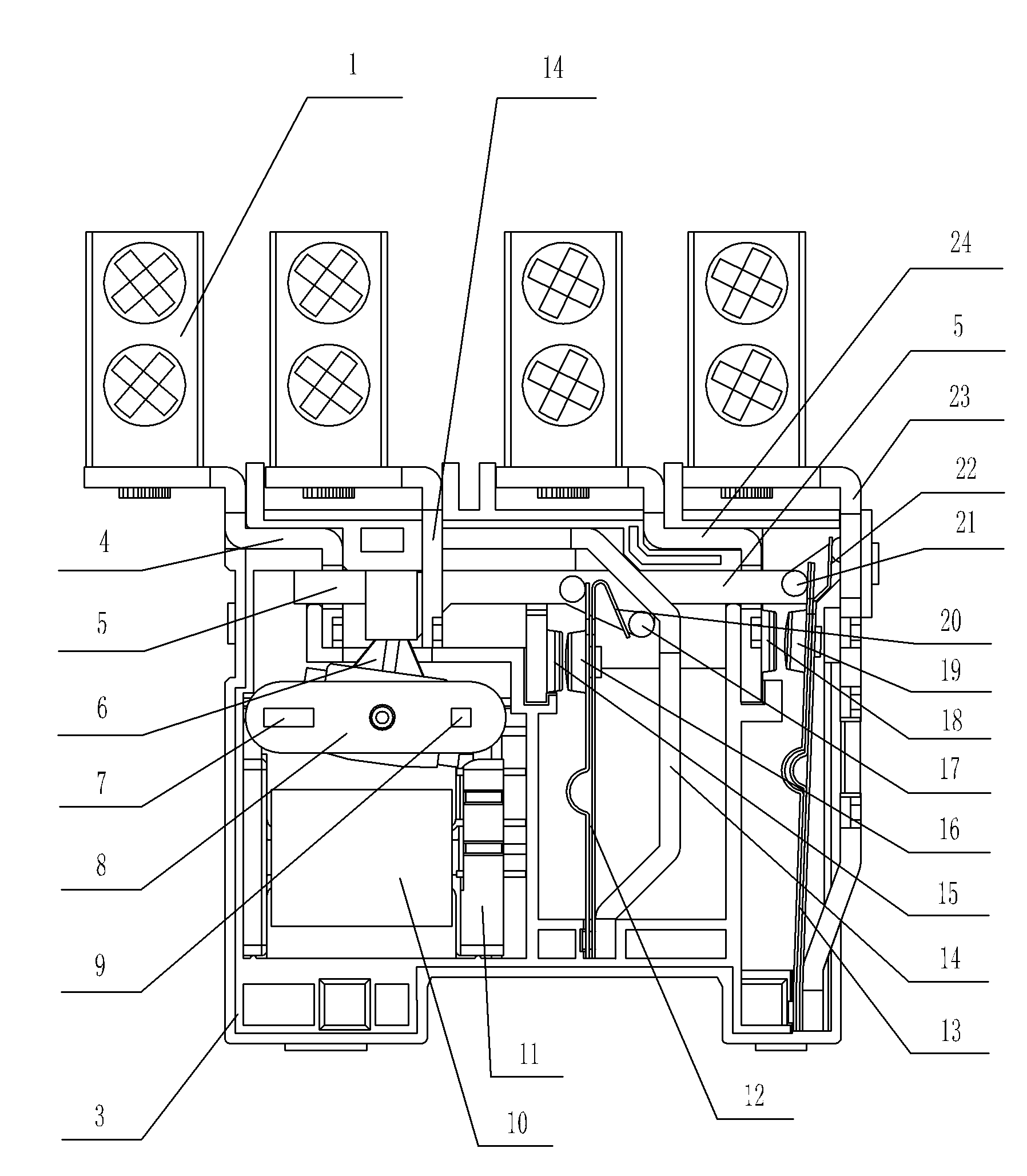
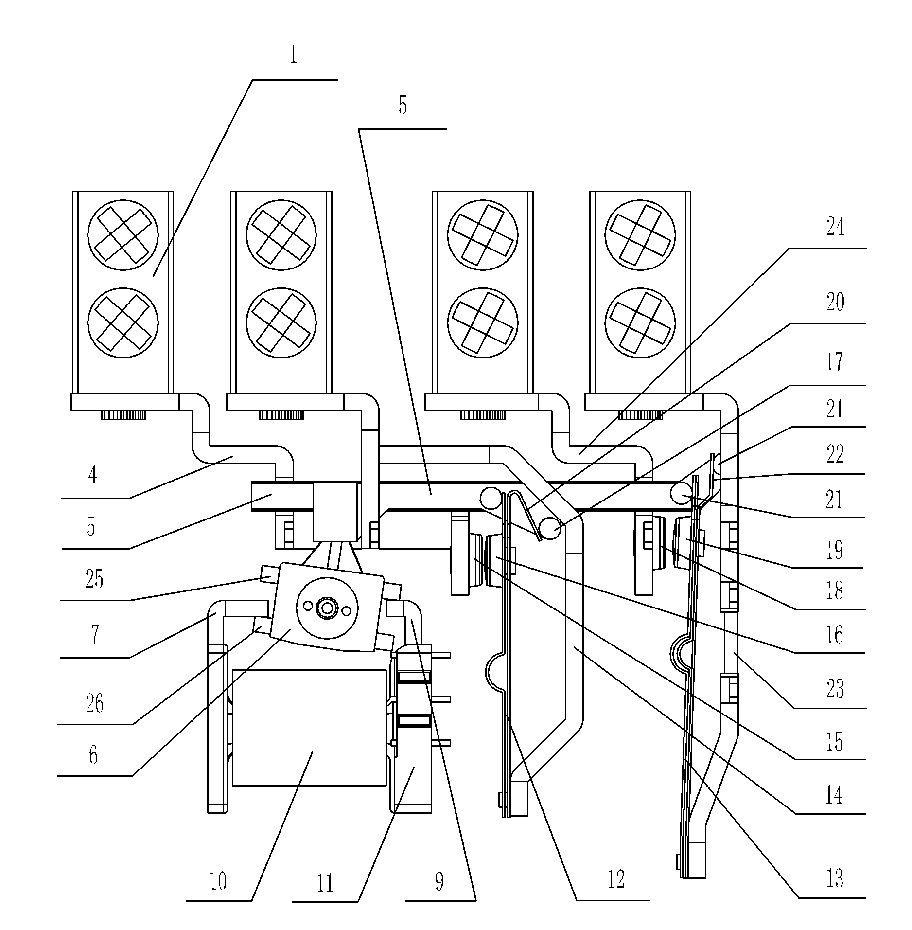
[0014] Such as figure 1 , figure 2 with image 3 As shown, in this specific embodiment, the relay of the present invention includes a base 3, a rear cover 2, a moving reed I 12, a moving reed II 13, a skeleton 11, a coil 10 connected to the skeleton 11, and from left to right The static contact piece I 4 , the moving spring lead-out piece I 14 , the static contact piece II 24 and the moving spring lead-out piece II 23 are sequentially connected to the base 3 . The static contact piece I 4, the moving spring lead-out piece I 14, the static contact piece II 24 and the upper part of the moving spring lead-out piece II 23 are all connected to a terminal 1, the base 3 is connected with the back cover 2, and the static contact piece I 4 The upper part is connected with the static contact I 15, the lower part of the movable reed I 12 ...
PUM
Abstract
The invention discloses a relay, comprising a base, a rear cover, a movable contact spring I, a movable contact spring II, a framework, a coil connected on the framework, a static contact spring I, a movable leading-out spring I, a static contact spring II and a movable leading-out spring II, wherein the static contact spring I, the movable leading-out spring I, the static contact spring II and the movable leading-out spring II are sequentially connected on the base from left to right; the base is connected with the rear cover, the static contact spring I is connected with a static contact I, the lower part of the movable contact spring I is connected with the movable leading-out spring I, the upper part of the movable contact spring I is connected with a movable contact I capable of being sucked on the static contact I, the static contact spring II is connected with a static contact II, the lower part of the movable contact spring II is connected with the movable leading-out spring II, the upper part of the movable contact spring II is connected with a movable contact II capable of being sucked on the static contact II, the polarity of the coil can be changed, the framework is positioned at the left of the movable contact spring I, and a retention mechanism, which can retain the movable contact spring I and the movable contact spring II in the state that the coil is power on after the coil is power off, is arranged between the framework and the movable contact spring I as well as the movable contact spring II. The invention can save electric energy and prolong the service life of the coil.
Description
Technical field: [0001] The invention relates to an electronic control device, specifically a relay. Background technique: [0002] We know that when the relay in the conventional technology is working, as long as a certain voltage is applied to both ends of the coil, a certain current will flow through the coil, thereby generating an electromagnetic effect, and the armature will drive the reed to move under the action of electromagnetic force. The moving contact of the moving contact and the static contact (normally open contact) on the static reed are sucked together. After the moving contact and the static contact are pulled together, the external circuit is connected. In order to keep the external circuit in a conducting state, we need Continue to supply power to the coil to keep the moving contact and the static contact closed. However, supplying power to the coil for a long time will not only cause a waste of electric energy, but also cause the heat generation of the c...
Claims
Application Information
Patent Timeline
Application Date:The date an application was filed.
Publication Date:The date a patent or application was officially published.
First Publication Date:The earliest publication date of a patent with the same application number.
Issue Date:Publication date of the patent grant document.
PCT Entry Date:The Entry date of PCT National Phase.
Estimated Expiry Date:The statutory expiry date of a patent right according to the Patent Law, and it is the longest term of protection that the patent right can achieve without the termination of the patent right due to other reasons(Term extension factor has been taken into account ).
Invalid Date:Actual expiry date is based on effective date or publication date of legal transaction data of invalid patent.