Outlet structure of power line for driving motor of electric vehicle

A technology for driving motors and electric vehicles. It is applied in the direction of electric vehicles, motors, and electric components. It can solve the problems of reduced heat dissipation performance, high cost of mold opening, and small size of permanent magnet motors, so as to improve the sealing performance and protection level. Improving the performance of the motor and improving the performance of the vehicle

Inactive Publication Date: 2010-09-15
SHANGHAI ZHONGKE SHENJIANG ELECTRIC VEHICLE
View PDF2 Cites 10 Cited by
  • Summary
  • Abstract
  • Description
  • Claims
  • Application Information

AI Technical Summary

Problems solved by technology

The drive motors of existing electric vehicles generally use permanent magnet motors, but the small size of permanent magnet motors leads to reduced heat dissipation performance and the risk of magnet demagnetization at high temperatures. In order to improve heat dissipation performance and avoid the risk of magnet demagnetization, heat transfer oil is added to the motor cavity After that, the temperature of the magnetic steel can be effectively reduced, but when the internal temperature of the motor rises during operation, the air expands due to heat, causing the internal pressure of the motor to increase, and there is a risk of oil leakage at the position of the motor lead-out wire
[0004] The common solution is to increase the junction box to achieve the purpose of sealing, but the volume of the motor increases, and the protection level of the motor cannot reach IP55. Some manufacturers also use mold opening to achieve the purpose of sealing the terminal. The structure is complex and the cost of mold opening is high

Method used


Image

  • Outlet structure of power line for driving motor of electric vehicle
  • Outlet structure of power line for driving motor of electric vehicle

Examples


Embodiment Construction

[0026] In order to understand the technical content of the present invention more clearly, the following examples are given in detail. In this case, the same components are provided with the same reference numerals.

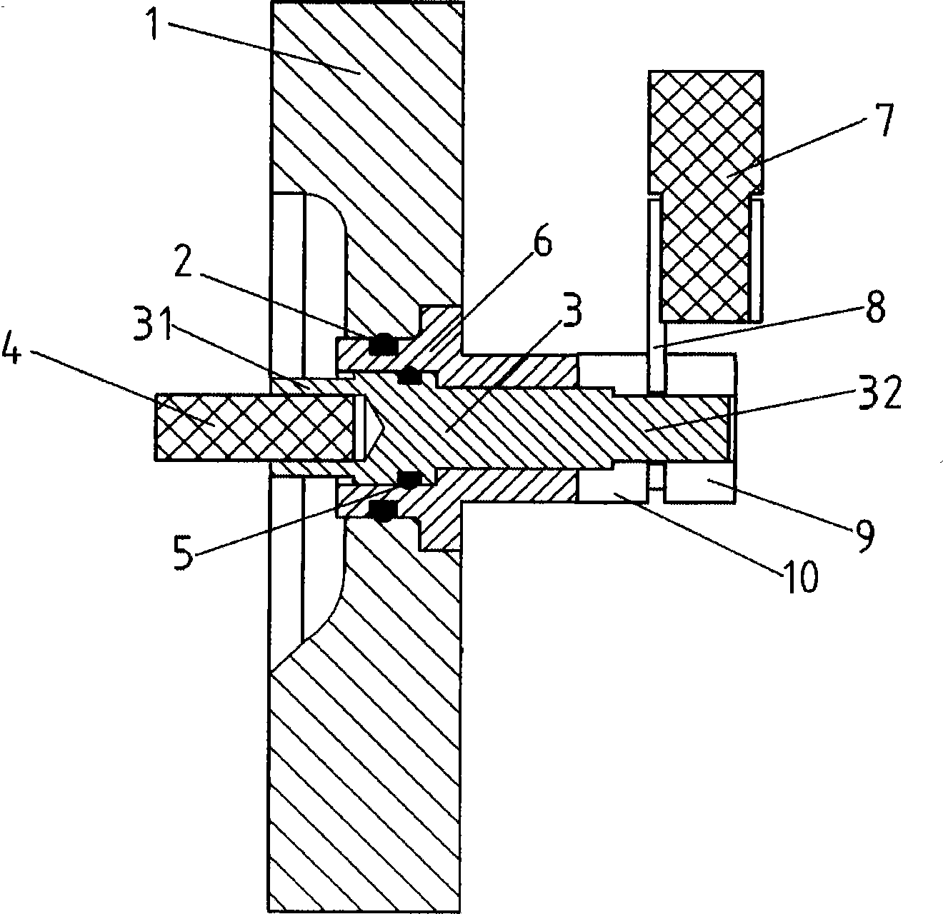
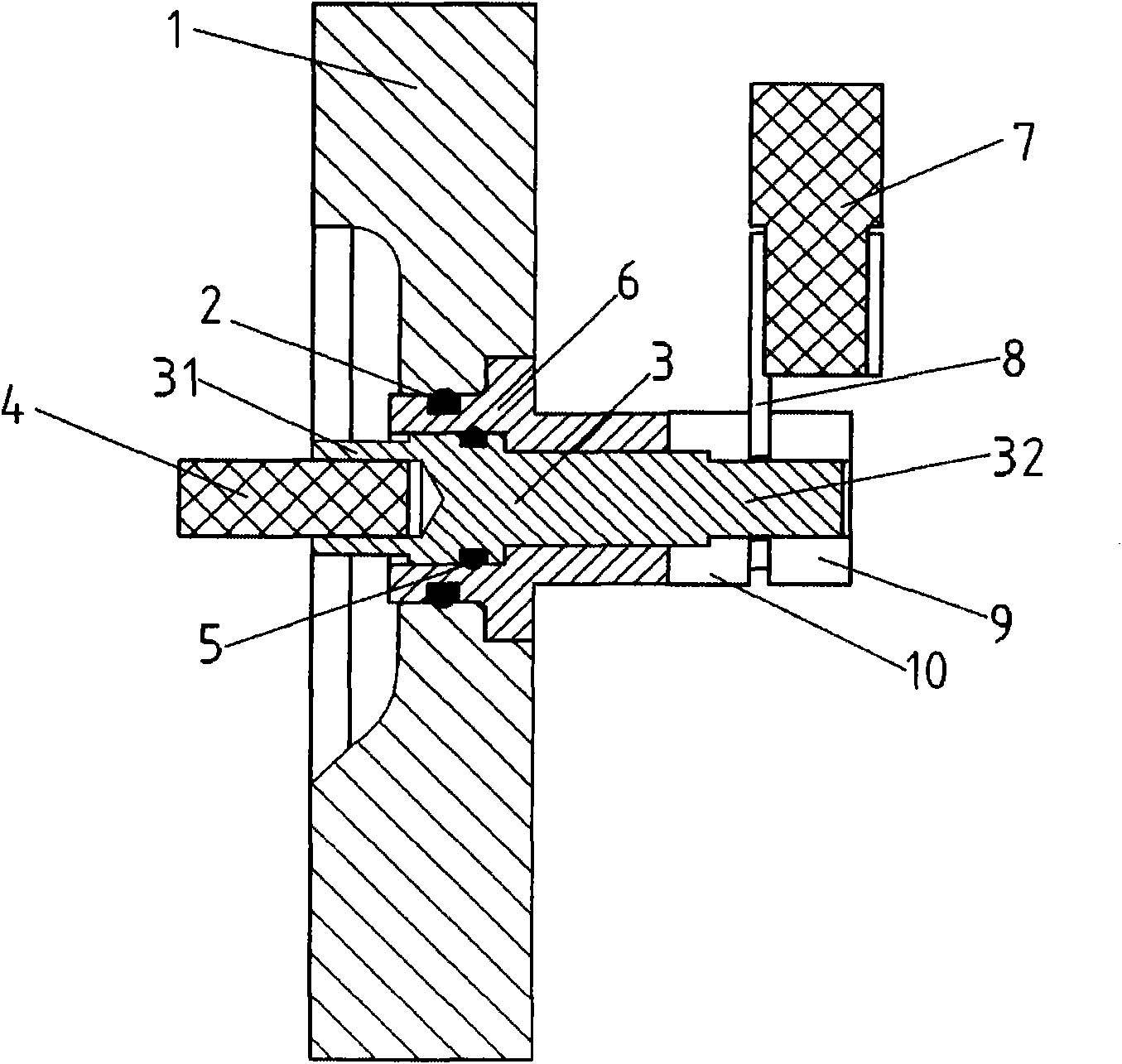
[0027] See figure 1 As shown, the electric vehicle drive motor power line outlet structure of the present invention includes a terminal 3 and an insulating adapter 6, the terminal 3 includes a first end 31 and a second end 32, and the insulating adapter 6 passes through The end cover 1 of the overdrive motor (not shown) is sealed and fixedly connected with the end cover 1, and the terminal post 3 passes through the insulating adapter 6 and is sealed and fixedly connected with the insulating adapter 6. The first end portion 31 is located inside the driving motor and is electrically conductively connected to the lead wire 4 of the driving motor, and the second end portion 32 is located outside the driving motor and is electrically conductively connected to the ext...


PUM


Abstract

The invention relates to an outlet structure of a power line for a driving motor of an electric vehicle. An insulated adapter of the outlet structure passes through an end cap of the driving motor and is in sealing and fixed connection with the end cap, a binding post passes through the insulated adapter and is in sealing and fixed connection with the insulated adapter, the first end of the binding post is positioned in the driving motor and is conducted and connected with an outlet circuit of the driving motor, and the second end of the binding post is positioned outside the driving motor and is conducted and connected with an external cable circuit; preferably, the insulated adapter is in sealing connection with the end cap through an adapter sealing ring, the insulated adapter and the end cap are fixedly connected through thread engagement, the binding post is in sealing connection with the insulated adapter through a binding post sealing ring, and the binding post and the insulated adapter are fixedly connected by adopting fixed conducting nuts. The invention has the advantages of simple structure, small volume, light weight and high safety and simultaneously improves the sealing performance and the protection grade of the driving motor, thereby improving the performance of the motor, finally improving the performance of the whole vehicle, and being suitable for large-scale generalization and application.

Description

technical field [0001] The invention relates to the technical field of electric vehicle drive systems, in particular to the technical field of the driving motor part of the electric vehicle drive system, and in particular to a power line outlet structure for the electric vehicle drive motor. Background technique [0002] The impact of fuel vehicles on the environment is becoming more and more obvious. New energy electric vehicles must be developed to replace fuel vehicles in order to reduce environmental pollution and reduce the impact on human health. [0003] At present, a series of electric vehicles have also been launched on the market. However, since the mileage of an electric vehicle depends entirely on the energy provided by the battery of the electric vehicle itself, the components of the electric vehicle are required to be small in size and light in weight. As the main power source of electric vehicles, the drive motor directly affects the performance of the vehicl...

Claims


Application Information

Patent Timeline
Patent Type & Authority Applications(China)
IPC IPC(8): H02K5/22H02K5/10
CPCY02T10/641Y02T10/64
Inventor 廖肖峰顾凌云罗建陈自伟
Owner SHANGHAI ZHONGKE SHENJIANG ELECTRIC VEHICLE
Why Eureka
Try Eureka