Display method and display device of large-scale network node topological structure

A technology of network nodes and topology structure, applied in the network field, can solve the problems of unintuitive efficiency, low efficiency, and it is difficult to visually see the connection relationship of nodes, etc., and achieve the general effect of solution implementation.

Inactive Publication Date: 2010-09-15
BEIJING VENUS INFORMATION TECH +1
View PDF0 Cites 36 Cited by
  • Summary
  • Abstract
  • Description
  • Claims
  • Application Information

AI Technical Summary

Problems solved by technology

It can be imagined that if there are tens of thousands of network nodes and tens of millions of connection relationships in the entire WAN, the entire topology map displayed directly at one time may not be what the user really wants to see, and may not be able to be efficiently and quickly Display topology diagram
In addition, if the user only needs to pay attention to the topology diagram within a certain level, then the one-time display method may not be able to meet the needs of the customer; even if it is displayed, it is difficult for the user to see the nodes clearly in the complex node relationship connection between
Obviously, for the network environment of large-scale wide area network, it is unintuitive and inefficient to display it at one time regardless of level

Method used


Image

  • Display method and display device of large-scale network node topological structure
  • Display method and display device of large-scale network node topological structure
  • Display method and display device of large-scale network node topological structure

Examples


Embodiment 1

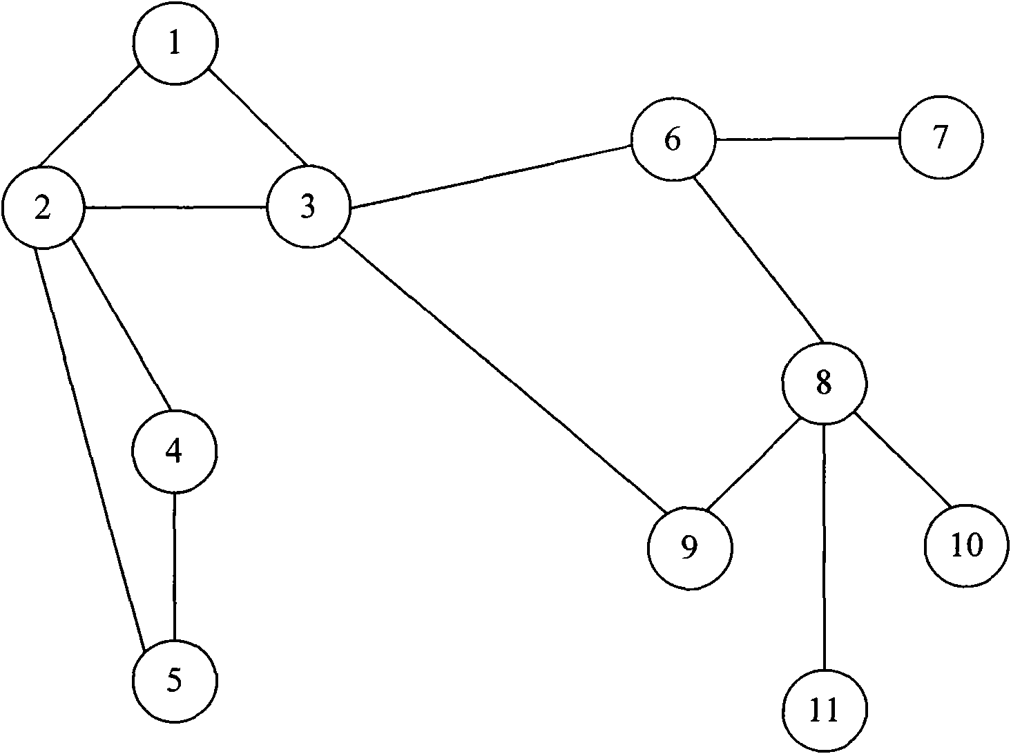
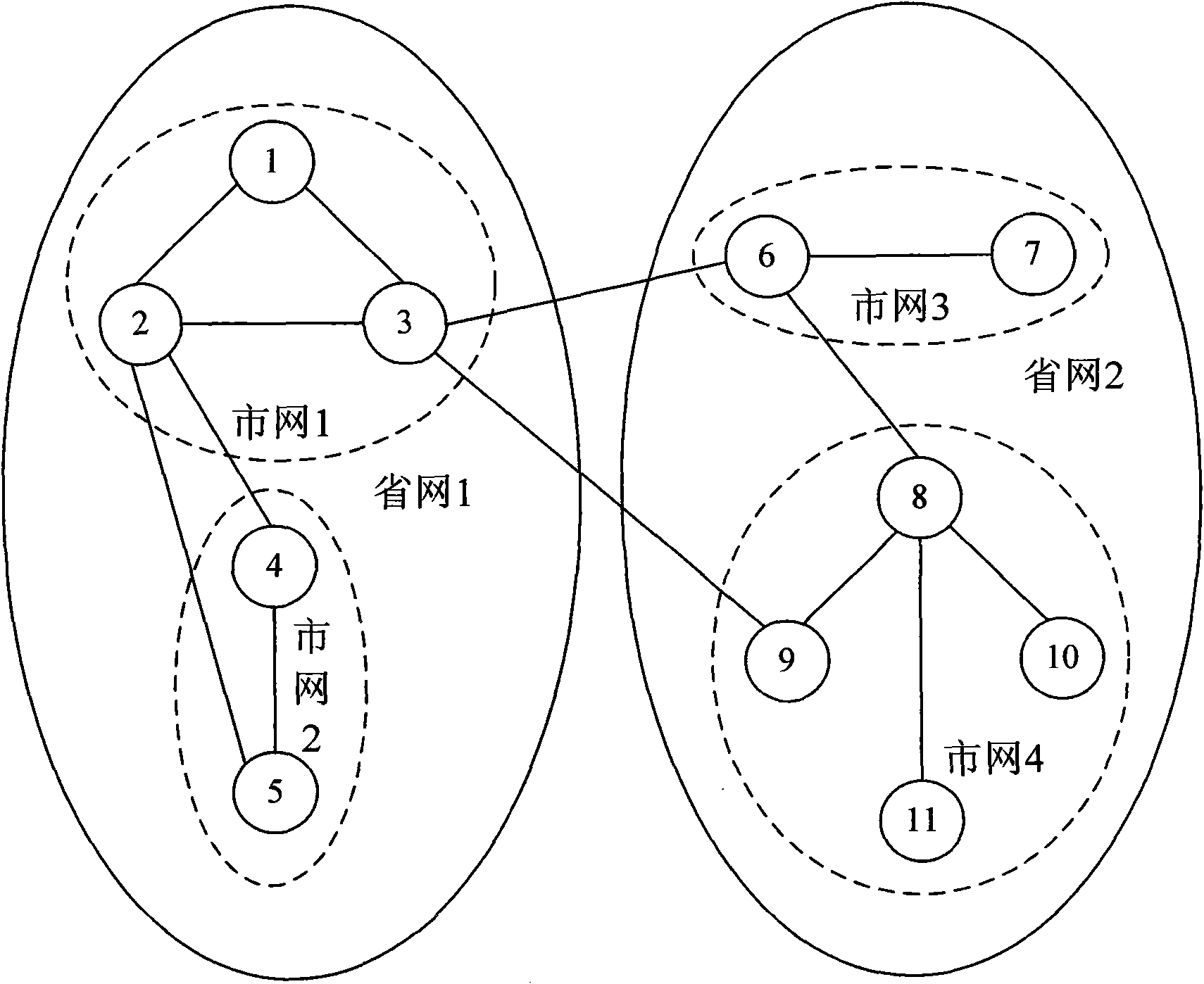
[0085] Embodiment 1, nodes in the system such as figure 2 As shown, it is divided into three levels, from high to low: first-level nodes provincial network 1 and provincial network 2, second-level nodes city network 1 to city network 4, and ordinary nodes 1 to 11, according to the network node level relationship, the system presents at least three types of node icons, which are first-level icons, second-level icons, and common node icons. Multiple ordinary nodes belong to a second-level node, and multiple second-level nodes belong to a first-level node.

[0086] In this case, the method of this embodiment specifically includes the following steps:

[0087]S1. System initialization, including: system global variable initialization, hierarchical drop-down box initialization, mouse right-click menu initialization, etc.;

[0088] S2. Sending an HTTP request: this embodiment is based on the architecture mode of client / server. The node data is stored in the database DB on the se...

Embodiment 2

[0153] Embodiment 2, in this embodiment will show a such as figure 2 The network topology diagram shown. Such as figure 2 As shown, this topology diagram includes 11 common nodes, 4 secondary nodes and 2 primary nodes. According to the principle that "multiple ordinary nodes belong to a second-level node, and multiple second-level nodes belong to a first-level node", the data of the first-level nodes and second-level nodes in this topology diagram can be represented by the following two tables :

[0154] Table 1. First-level node data

[0155] Level 1 node code (lev1Code)

First level node description

100000

Provincial network 1

[0156] Level 1 node code (lev1Code)

First level node description

200000

Provincial network 2

[0157] Table 2. Secondary node data

[0158] Secondary node code (lev2Code)

Secondary node description

The first-level node code to which it belongs

100001

C...


PUM


Abstract

The invention discloses a display method and a display device of a large-scale network node topological structure. The display method comprises the following steps of: loading node data and relational data of nodes in a network, wherein the node data comprises nodes of all levels and subordination relations among the nodes, and the relational data is used for indicating connection relations among the nodes; when a user selects a node as an attention node, displaying child nodes of the attention node, same-level nodes which have connection relations with the attention node and belong to the same father node and nodes which have connection relations with the attention node and the levels higher than that of the attention node according to the node data; and displaying connection relations among the displayed nodes according to the relational data. The invention can visually show the topological structure of the attention node, and enable the showing efficiency to improve.

Description

technical field [0001] The invention relates to the network field, in particular to a display method and a display device for a large-scale network node topology. Background technique [0002] With the popularity and rapid development of the Internet (Internet), the scale of the network is getting bigger and bigger, and the network structure is getting more and more complex. In order to facilitate network management personnel to manage and maintain a huge network, the network topology can usually be displayed graphically on the network management device. [0003] In order to accurately display the network topology, it is necessary to record the relationship data (also called associative data) and hierarchical relationship of network nodes. From this, it is possible to display network topology diagrams based on relational data and hierarchical relationships. [0004] figure 1 It is a topology diagram of a simple network. Such as figure 1 As shown, each circle represents ...

Claims


Application Information

Patent Timeline
Patent Type & Authority Applications(China)
IPC IPC(8): H04L12/24H04L29/06H04L29/08
Inventor 黄东
Owner BEIJING VENUS INFORMATION TECH
Why Eureka
Try Eureka