A network topology layout method and device

A technology of network topology and layout method, which is applied in the field of transmission network and can solve problems such as low layout efficiency

Active Publication Date: 2018-02-23
XINYANG BRANCH HENAN CO LTD OF CHINA MOBILE COMM CORP
View PDF3 Cites 0 Cited by
  • Summary
  • Abstract
  • Description
  • Claims
  • Application Information

AI Technical Summary

Problems solved by technology

[0005] The embodiment of the present invention provides a network topology layout method and equipment to solve the problem of low layout efficiency in the prior art when the network topology layout is performed manually

Method used


Image

  • A network topology layout method and device
  • A network topology layout method and device

Examples


Embodiment 1

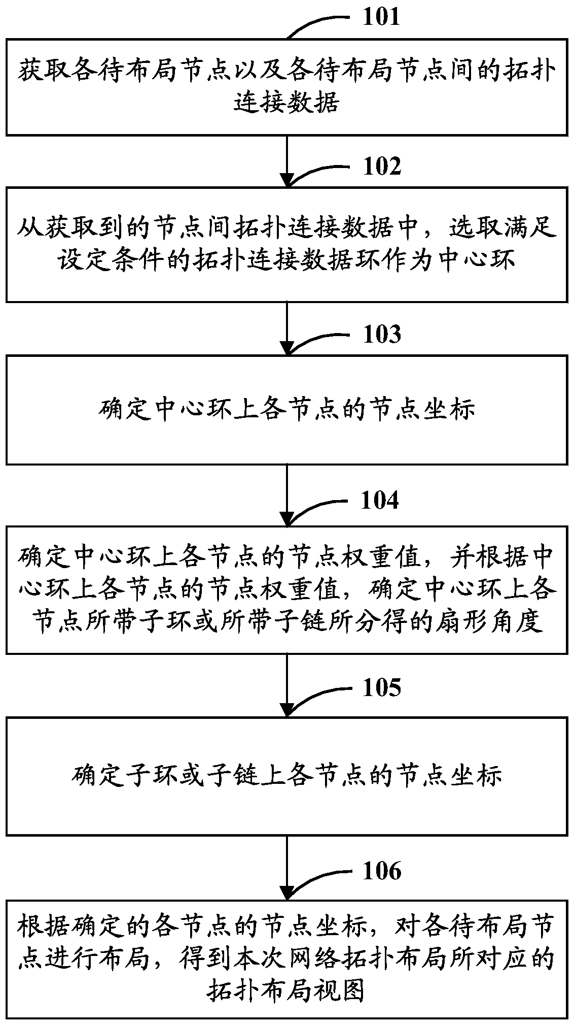
[0028] Such as figure 1 As shown, it is a schematic flow chart of the network topology layout method described in Embodiment 1 of the present invention. The network topology layout method is applicable to the field of transmission network technology, and this embodiment of the present invention does not make any limitation thereto; specifically, the The network topology layout method may include the following steps:

[0029] Step 101: Obtain each node to be laid out and topological connection data between the nodes to be laid out.

[0030] Specifically, in the embodiment of the present invention, the acquired nodes to be deployed are all non-isolated nodes, and the acquired nodes to be deployed may include routers, switches, hubs and other transmission network elements. One or more, which is not limited in the embodiments of the present invention.

[0031] Further, in the embodiment of the present invention, the obtained inter-node topological connection data is usually a to...

Embodiment 2

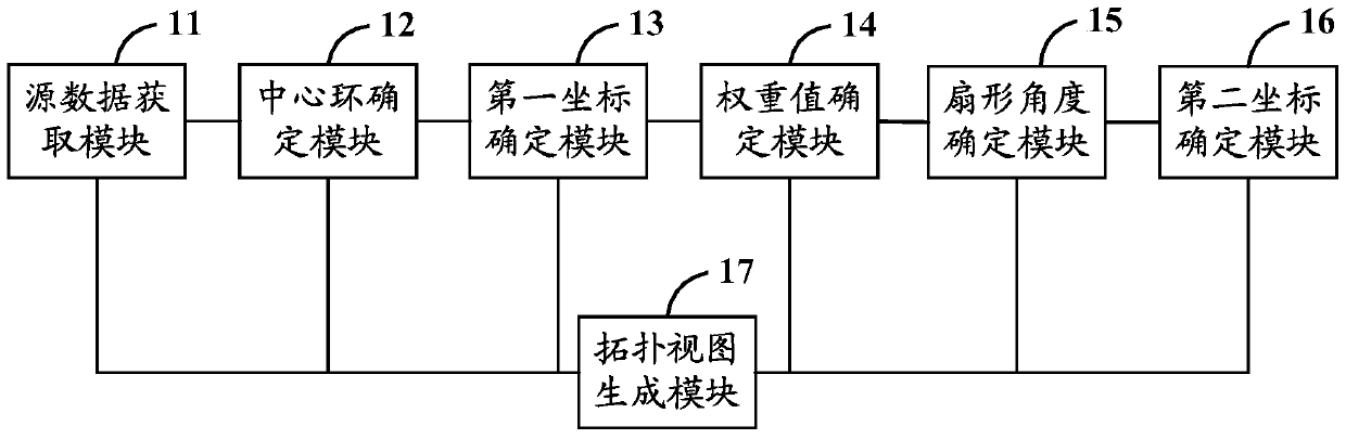
[0101] Such as figure 2 As shown, it is a schematic structural diagram of the network topology layout device described in Embodiment 2 of the present invention. The network topology layout device is applicable to the field of transmission network technology, and this embodiment of the present invention does not make any limitation thereto; specifically, the The network topology layout device may include a source data acquisition module 11, a center ring determination module 12, a first coordinate determination module 13, a weight value determination module 14, a sector angle determination module 15, a second coordinate determination module 16 and a topology view generation module 17, in:

[0102] The source data acquisition module 11 is used to acquire the nodes to be laid out and the topological connection data between the nodes to be laid out; specifically, in the embodiment of the present invention, the obtained topological connection data between the nodes usually include...


PUM


Abstract

The invention discloses a method and equipment for network topology layout. According to the level of topology connection rate of each topology connection data ring in the topology connection data between nodes, the high-speed level topology connection data ring is used as the central ring to lay out in the center of the view position, and through determining the node coordinates of each node on the central ring, analyzing the node weight value of each node on the central ring, determining the fan angle of the sub-rings or sub-chains attached to the central ring, and determining the sub-rings attached to the central ring The node coordinates of each node on the ring or the attached sub-chain are calculated to obtain the node coordinates of each node to be laid out, and according to the calculated node coordinates of each node to be laid out, the layout of each node to be laid out is carried out, so that in On the basis of clearly reflecting the network hierarchical structure of the transmission network, the automatic layout of the network topology of the transmission network is realized, and the layout efficiency of the network topology layout is improved.

Description

technical field [0001] The present invention relates to the technical field of transmission network, in particular to a transmission network-based network topology layout method and equipment. Background technique [0002] The transmission network is a comprehensive information transmission network that integrates multiplexing, line transmission and switching functions and is operated and managed by a unified management system. It can realize business performance monitoring, dynamic network maintenance, and connection and intercommunication between equipment of different operators Multiple network management functions can significantly reduce the cost of network management and maintenance while greatly improving the utilization rate of network resources, thereby realizing flexible, reliable and efficient network operation and maintenance. [0003] Based on the above-mentioned functions of the transmission network, the transmission network occupies an increasingly important p...

Claims


Application Information

Patent Timeline
Patent Type & Authority Patents(China)
IPC IPC(8): H04L12/46H04L12/751H04L45/02
Inventor 吴荣宇崔凯李阳
Owner XINYANG BRANCH HENAN CO LTD OF CHINA MOBILE COMM CORP
Why Eureka
Try Eureka