Infrared transmitter

一种红外发射机、红外线的技术,应用在红外发射机领域,达到电力使用效率提高的效果

Active Publication Date: 2010-09-15
AUDIO-TECHNICA
View PDF1 Cites 2 Cited by
  • Summary
  • Abstract
  • Description
  • Claims
  • Application Information

AI Technical Summary

Problems solved by technology

However, it is not an infrared transmitter that can change the bias current according to the output level of the transmitted signal

Method used


Image

  • Infrared transmitter
  • Infrared transmitter
  • Infrared transmitter

Examples


Embodiment Construction

[0031] Hereinafter, embodiments of the infrared transmitter of the present invention will be described with reference to the drawings.

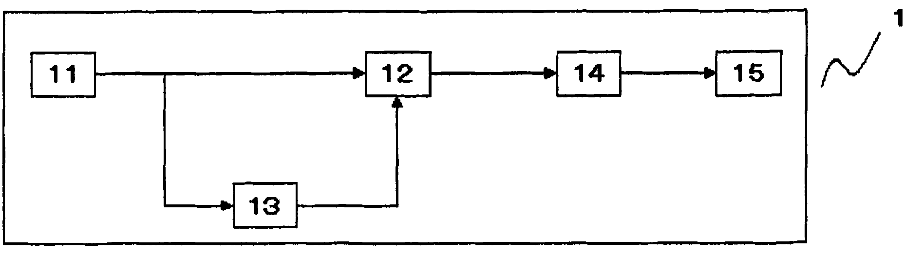
[0032] figure 1 It is a block diagram showing a configuration example of the infrared transmitter of the present invention. exist figure 1 Among them, the transmitter 1 includes a signal generation unit 11 , a signal voltage mixing unit 12 , a bias voltage generation unit 13 , a voltage-current conversion unit 14 and an optical signal transmission unit 15 . The signal generator 11 is means for generating a predetermined signal voltage when an unshown operation key is pressed, and outputs, for example, a predetermined sine wave signal for identifying the pressed operation key. The signal voltage mixing unit 12 is means for superimposing the voltage output from the bias voltage generating unit 13 on the signal voltage output from the signal generating unit 11 and outputting the signal voltage.

[0033] The bias voltage generator 13 is a me...


PUM


Abstract

An infrared transmitter is provided with a transmission signal generating means for transmitting a signal by changing luminance of an LED which emits infrared rays, a biasing voltage generating means for generating a biasing voltage corresponding to the size of the transmission signal, a signal / voltage mixing means for mixing the transmission signal and the biasing voltage, and a voltage-current conversion means for converting the voltage into a current. The infrared transmitter drives the LED by the current generated by the voltage-current conversion means and improves power use efficiency.

Description

technical field [0001] The invention relates to an infrared transmitter using an infrared light-emitting diode, which can improve power utilization efficiency. Background technique [0002] The infrared transmitter has a light emitting diode (hereinafter referred to as "LED") that emits infrared rays, and employs a light modulation method that changes the brightness of the LED in accordance with a transmitted signal. [0003] The brightness of the LED changes according to the magnitude of the driving current flowing through the LED, so the light modulation method is realized by converting the transmission signal into a current and using the current as the driving current. Therefore, if the bias current corresponding to 50% or more of the maximum amplitude level of the transmission signal is not supplied to the LED in advance, the fluctuation of the current converted from the transmission signal is saturated and accurate modulation cannot be performed. [0004] The relations...

Claims


Application Information

Patent Timeline
Patent Type & Authority Applications(China)
IPC IPC(8): H04B10/04H01L33/00H04B10/06H04B10/14H04B10/26H04B10/28H04B10/114
CPCH04B10/1141
Inventor 播磨辰治
Owner AUDIO-TECHNICA
Why Eureka
Try Eureka